Optical element and radiation detector using the same

A technology of optical elements and detectors, which is applied in the field of radiation detectors, can solve problems such as inability to meet large area, difficulty in large area of ​​light-receiving surface, and limitation of large-area light-receiving surface

Inactive Publication Date: 2002-03-27
HAMAMATSU PHOTONICS KK
View PDF1 Cites 4 Cited by
  • Summary
  • Abstract
  • Description
  • Claims
  • Application Information

AI Technical Summary

Problems solved by technology

That is to say, in the above-mentioned radiation detector, it is necessary to arrange a plurality of radiation detection units including the above-mentioned optical members of a special shape (triangular prism shape) so that the light-receiving surfaces thereof are arranged on the same plane, so it is not necessary to increase the area of ​​the light-receiving surface. Easy
In addition, due to restrictions on the arrangement of the imaging element, etc., there are restrictions on increasing the area of ​​the light-receiving surface, and it is impossible to achieve a sufficient area to meet the needs of medical and industrial applications.

Method used


Image

  • Optical element and radiation detector using the same
  • Optical element and radiation detector using the same
  • Optical element and radiation detector using the same

Examples


Embodiment Construction

[0012] best practice

[0013] A radiation detector according to an embodiment of the present invention will be described below based on the drawings. In addition, the size and shape in each drawing are not necessarily the same as the real thing, and some parts are enlarged for easy understanding.

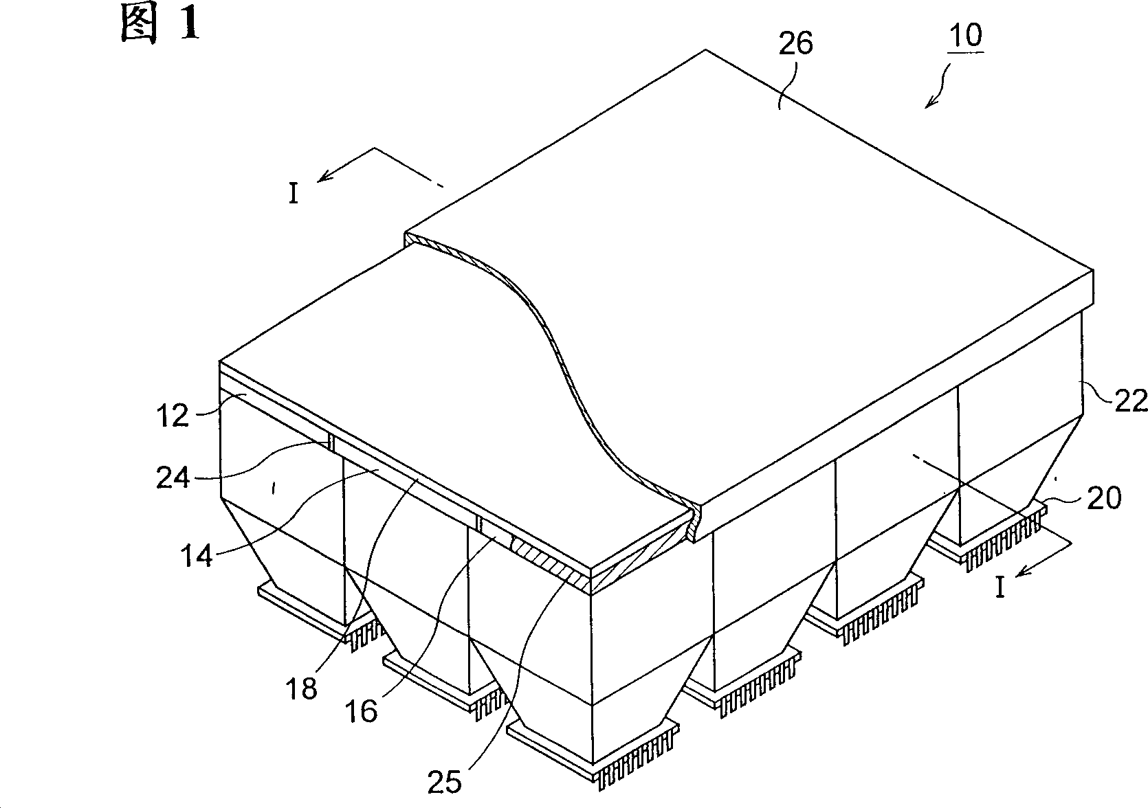
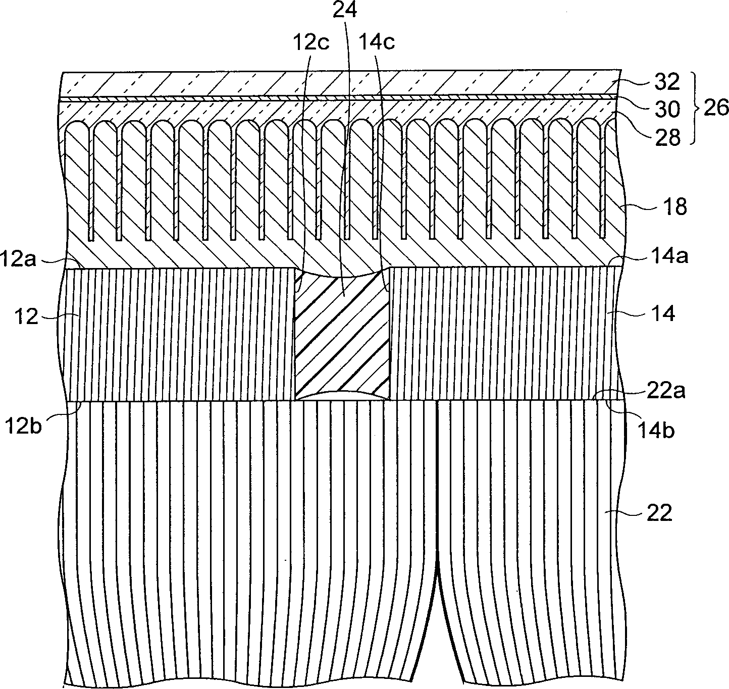
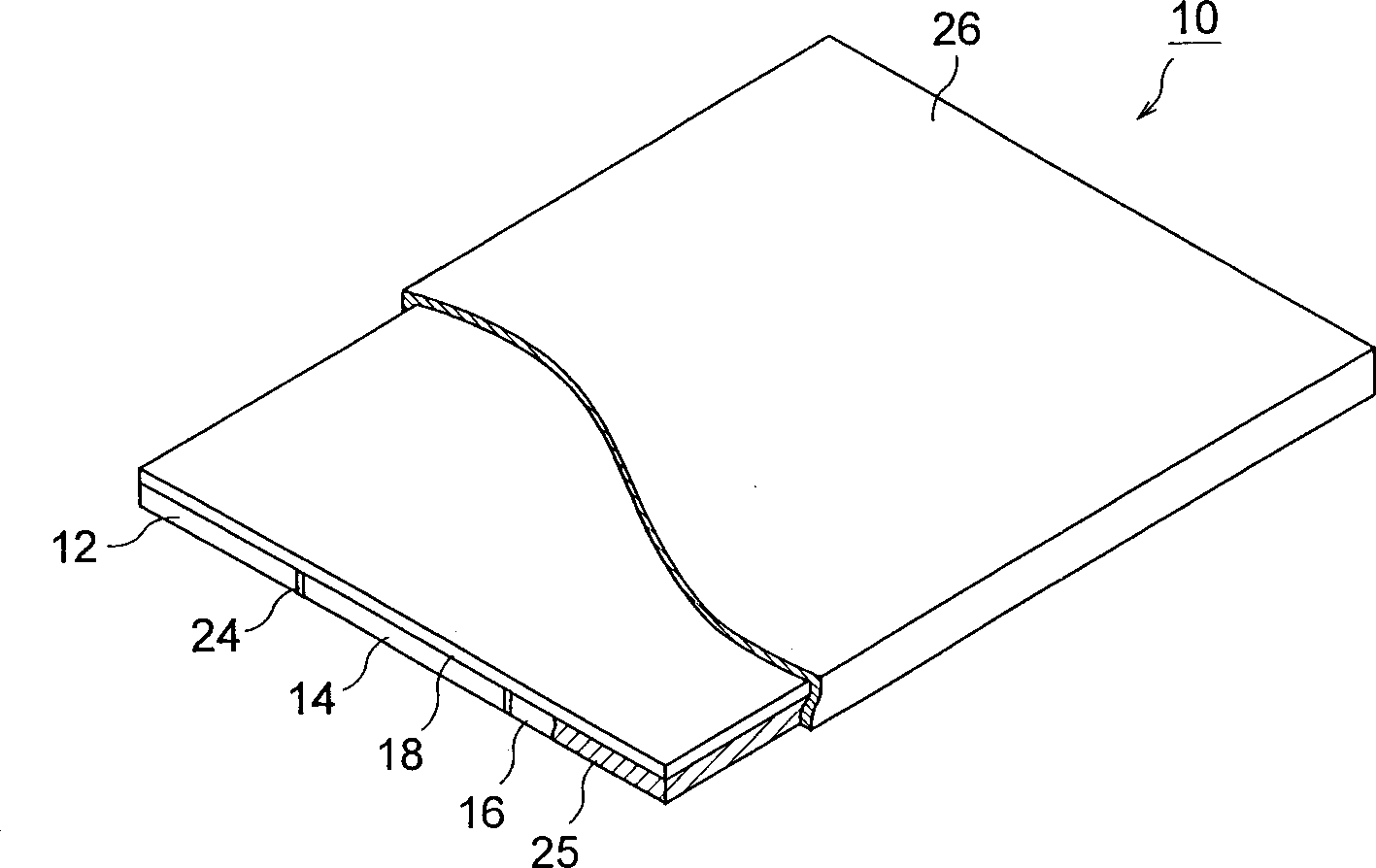
[0014] First, the configuration of the radiation detector according to the present embodiment will be described. FIG. 1 is a perspective view of a radiation detector according to the present embodiment, figure 2 It is a partially enlarged cross-sectional view along line I-I in FIG. 1 . Furthermore, the optical element of the present invention is included in the radiation detector according to the present embodiment, and if expressed separately from the radiation detector according to the present embodiment, it becomes image 3 shown in .

[0015] The radiation detector 10 according to this embodiment is configured to include: three optical members 12, 14, 16 arranged so that the...


PUM


Abstract

A radiation detector comprising three optical members having their light incident end faces (12a, 14a, 16a) arranged in almost the same plane, a scintillator mounted on the light incident end faces (12a, 14a, 16a) of the optical members, a plurality of CCDs for picking up optical images output from light outgoing end faces (12b, 14b, 16b) of the optical members and a plurality of light guiding optical members for guiding the optical images output from the light outgoing end faces (12b, 14b, 16b) of the optical members to the CCDs, wherein the optical members are securely bonded together with a clearance of 10-15 um by an adhesive that has a light adsorbin characteristic, and a protective film is provided over the scintillator.

Description

technical field [0001] The present invention relates to an optical element and a radiation detector using the same, and more particularly to a radiation detector having a large-area light receiving portion and an optical element used therefor. Background technique [0002] In fields such as medical treatment and industry, there is an increasing need for radiation detectors that detect and capture radiographic images quickly and with high precision. For example, a radiation detector equipped with a scintillator for converting a radiographic image into an optical image, an imaging element for imaging such an optical image, and a light guiding optical member for guiding the optical image output from the scintillator to the imaging element is known. of. [0003] In addition, as the above-mentioned optical member for light guide, several million pieces / cm are often arranged in parallel to each other. 2 Optical components formed integrally with optical fibers. Because this kind...

Claims


Application Information

Patent Timeline
IPC IPC(8): G01T1/20
CPCG01T1/2002G01T1/2018G01T1/20189G01T1/20185H01L27/14
Inventor 楠山泰野中克俊
Owner HAMAMATSU PHOTONICS KK
Why Eureka
Try Eureka