Motor

A technology for a motor and a driving coil, applied in the field of motors, can solve the problems of complex motor installation structure, inability to install the motor, and difficulty in obtaining rigidity, and achieve the effects of miniaturization, cost reduction, and plane rigidity improvement.

Inactive Publication Date: 2002-05-01
SANKYO SEIKI MFG CO LTD
View PDF1 Cites 3 Cited by
  • Summary
  • Abstract
  • Description
  • Claims
  • Application Information

AI Technical Summary

Problems solved by technology

[0004] However, even in the above-mentioned existing proposed device, there is a problem that the end portion of the drive coil must be looped around each terminal portion 2a side of the metal wiring boards 2, 2..., and the connection operation is cumbersome. At the same time, it is difficult to obtain the rigidity required for the motor substrate 1 made of synthetic resin, so the motor cannot be mounted on the motor substrate 1 as a standard, and the mounting structure of the motor is complicated and enlarged.

Method used


Image

  • Motor
  • Motor
  • Motor

Examples


Embodiment Construction

[0033] Embodiment of the invention

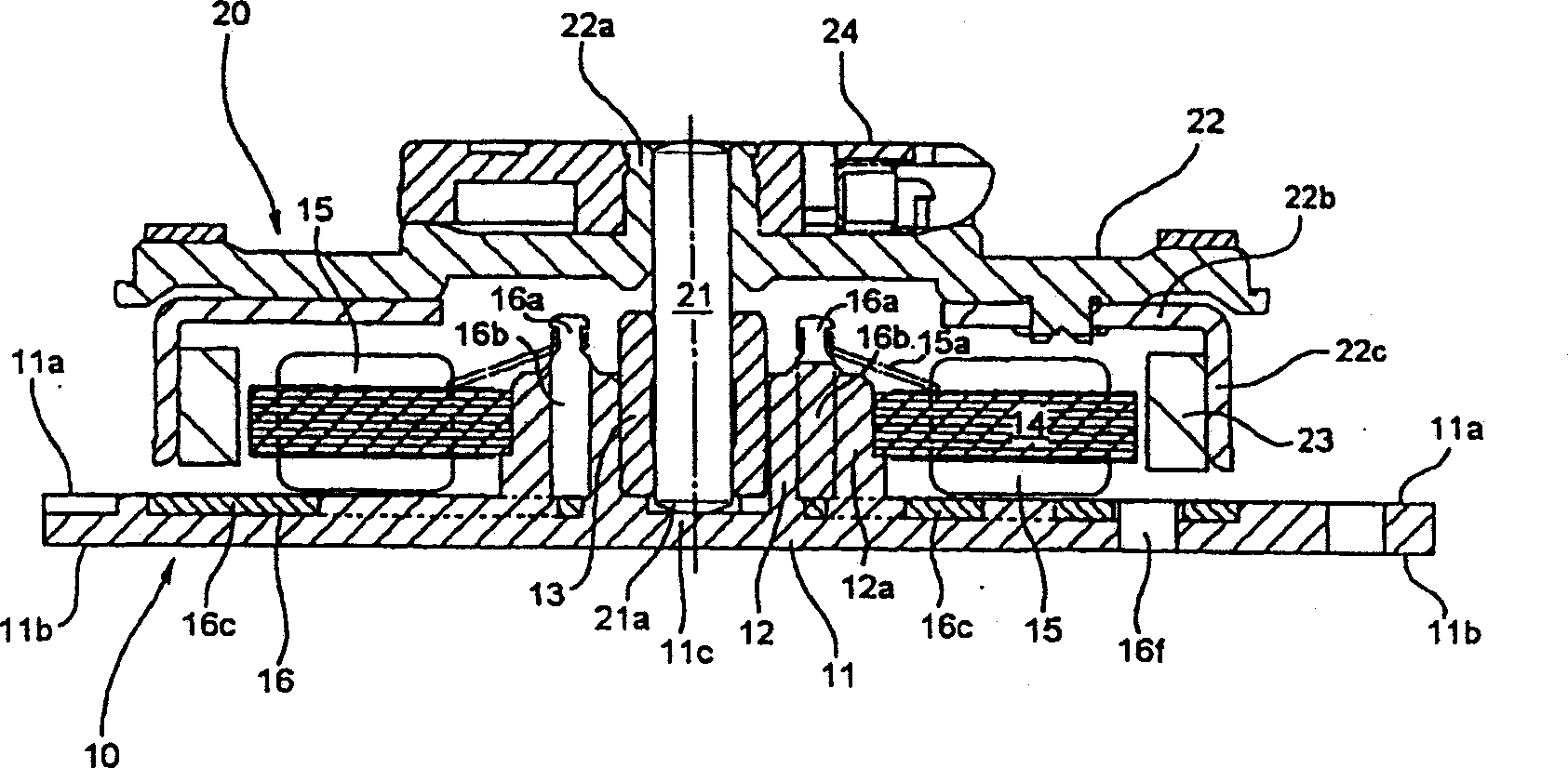
[0034] Embodiments to which the present invention is applied will be described below with respect to a spindle motor that can be used in various media drive rotary drive devices such as CD-ROMs.

[0035] figure 1 and figure 2 The illustrated spindle motor for a shaft-rotating type media drive driving device is generally composed of a stator group 10 as a fixed member, and a rotor group 20 axially attached to the stator group 10 as a rotating member.

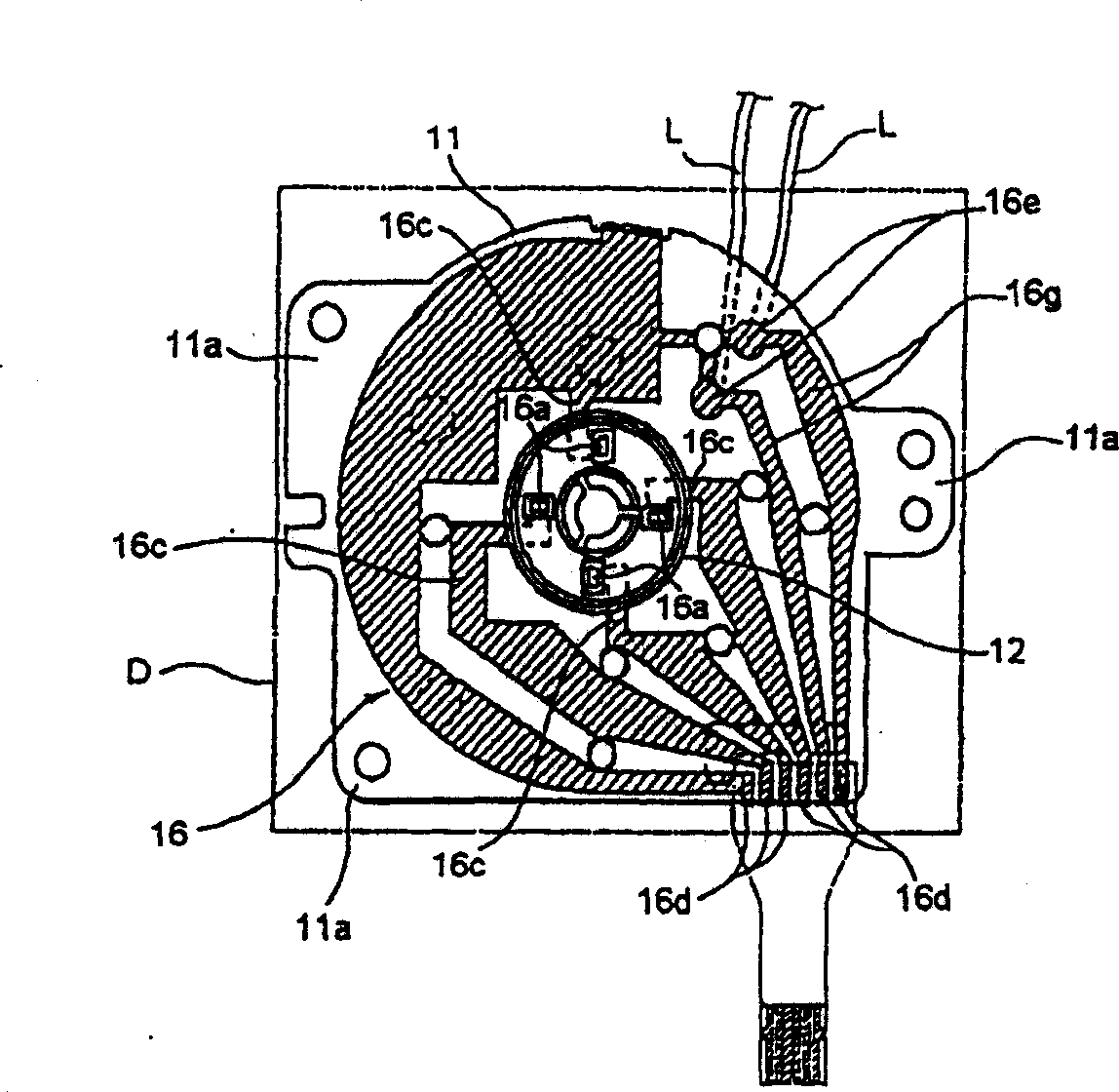
[0036] Among them, the stator group 10 is provided with a motor substrate 11 made of a synthetic resin plate-shaped member, and the reference surface 11b mounted on the motor mounting portion 11a of the motor substrate 11 is positioned by abutting against the main body device D side, and at the same time Secure the entire motor.

[0037] A substantially cylindrical bearing holder 12 is integrally provided at a substantially central portion of the motor substrate 11, and a metal bearing 13...


PUM


Abstract

Respective terminal parts 16a of a plurality of metal wiring boards 16 are arranged in the vicinity of respective terminal parts 15a of a plurality of drive coils 15, arranged in the circumferential direction by arranging the respective terminal parts 16a of a plurality of the metal wiring boards 16 in the same circumferential direction at substantially equal intervals, and the respective terminal parts 15a of the drive coils 15 are connectable easily with the respective terminal parts 16a of the metal wiring boards 16. The continuity parts 16c of the respective metal wiring boards 16 are extended, so as to surround the periphery of the terminal parts 16a, and the plane rigidity of a motor base plate 11, embedded with the metal wiring boards 16 can be improved and perform attaching work of the whole motor efficiently and highly accurately.

Description

technical field [0001] The present invention relates to a motor having a structure in which a drive coil is connected to a metal wiring board terminal portion buried inside a motor substrate. Background technique [0002] Generally, in a motor in which a multiphase drive coil is mounted on a stator core, each end portion drawn from the multiphase drive coil is soldered to a flexible circuit board by soldering or the like. Also, in JP-A-10-127031, etc., a motor has been proposed in which the terminal portion of the drive coil can be connected in a relatively large space. [0003] Among the electric motors relevant to this proposal, such as Figure 11 As shown, a plurality of conductive metal wiring boards 2, 2, . The terminal portion (commutator vertical piece) 2a is mounted in the axial direction in the core holding portion 3 integrally formed with the above-mentioned motor substrate 1 . According to the motor related to this type of proposal, it is possible to connect the...

Claims


Application Information

Patent Timeline
Patent Type & Authority Applications(China)
IPC IPC(8): H02K3/18H02K3/50H02K21/22
Inventor 赤羽诚武井宏光
Owner SANKYO SEIKI MFG CO LTD
Why Eureka
Try Eureka