Antenna feeding network comprising at least one holding element

a technology of holding elements and feeding networks, applied in the direction of polarised antenna unit combinations, coupling device connections, waveguides, etc., can solve the problems of reducing mechanical stability, unwanted radiation from feeding networks, reducing antenna performance in terms, etc., and achieves the effect of increasing permittivity and phase shi

Active Publication Date: 2020-12-08
CELLMAX TECH AB
View PDF39 Cites 0 Cited by
  • Summary
  • Abstract
  • Description
  • Claims
  • Application Information

AI Technical Summary

Benefits of technology

[0007]An object of the present invention is to overcome at least some of the disadvantages of the prior art described above. A further object is to provide an antenna feeding network which is easy to assemble.
[0012]The invention is based on the insight that smaller openings may be used without risking arcing or short circuit by providing insulating or dielectric holding elements in said openings through which connecting means to inner conductor(s) may be provided. The invention is further based on the insight that such a holding element may be configured to hold the inner conductor(s) in position for easier and more efficient connection to the inner conductor(s). The invention is further based on the insight that the performance of the antenna feeding network is dependent on the position of the inner conductors relative to the outer conductors, both laterally and longitudinally, and on the insight that a simplified antenna feeding network with fewer parts may be achieved by providing a holding element configured to hold the inner conductor(s) in the desired position rather than using separate components such as dielectric support means to position the inner conductor(s). The invention is further based on the insight that using such a holding element, if made in a dielectric material, may be configured to improve the impedance matching of the antenna arrangement.
[0017]In embodiments, where the antenna feeding network comprises at least two coaxial lines, at least two of the outer conductors of the coaxial lines are each provided with an opening, wherein the holding element is configured to be placed in the openings and engage and hold the inner conductors in the at least two outer conductors in position. In other words, the holding element fixates both the inner conductors. This is advantageous since it allows the two inner conductors to be conveniently interconnected. The holding element may be configured to hold the inner conductors in position in the longitudinal and / or sideways and / or lateral direction of the antenna feeding network. The at least two coaxial lines may be arranged in parallel. The at least two coaxial lines may be arranged adjacent each other.
[0027]The retaining mechanism may further comprise at least one laterally protruding nose portion of the holding element configured to abut against an outer surface portion of the outer conductor provided with an opening when the holding element is arranged in the opening. This is advantageous since it prevents the holding element from being pushed too deep into the opening.
[0029]In embodiments, at least one, or each, coaxial line of said at least one coaxial line is furthermore provided with at least one dielectric element to at least partially fill the cavity between the inner and outer conductors. Such dielectric element(s) is / are preferably slidably movable inside the outer conductor(s) to co-operate with the coaxial line(s) to provide a phase shifting arrangement. The phase shift is achieved by moving the dielectric element that is located between the inner conductor and the outer conductor of the coaxial line. It is a known physical property that introducing a material with higher permittivity than air in a transmission line will reduce the phase velocity of a wave propagating along that transmission line. This can also be perceived as delaying the signal or introducing a phase lag compared to a coaxial line that has no dielectric material between the inner and outer conductors. If the dielectric element is moved in such a way that the outer conductor will be more filled with dielectric material, the phase shift will increase. The at least one dielectric element may have a U-shaped profile such as to partly surround the inner conductor in order to at least partly fill out the cavity between the inner and outer conductors.
[0030]In embodiments, two of said at least two coaxial lines form a splitter / combiner. When operating as a splitter, the inner conductor of a first coaxial line is part of the incoming line, and the two ends of the inner conductor of the second coaxial line are the two outputs of the splitter. Thus, the second coaxial line forms two outgoing coaxial lines. In such an embodiment, the dielectric element may be arranged in the second coaxial line in such a way that by moving the dielectric part different amount of dielectric material is present in the respective outgoing coaxial lines. Such an arrangement allows the differential phase of the outputs of a splitter to be varied by adjusting the position of the dielectric part within the splitter. A reciprocal functionality will be obtained when the coaxial line functions as a combiner. Such splitters / combiners having variable differential phase shifting capability are advantageously used in an antennas having radiators positioned in a vertical column, to adjust the electrical antenna tilt angle by adjusting the relative phases of the signals feeding the radiators.

Problems solved by technology

It is however desirable to avoid or minimize openings in general in the outer conductors since openings, and large openings in particular, may result in reduced mechanical stability of the antenna, and may also influence the impedance properties negatively in the antenna feeding network, and may also result in unwanted radiation from the feeding network.
Such unwanted radiation may reduce the antenna performance in terms of e.g. back- or sidelobe suppression.
Openings in the outer conductor on the front side of the reflector may degrade antenna performance more than openings in the back side of the reflector.

Method used


Image

  • Antenna feeding network comprising at least one holding element
  • Antenna feeding network comprising at least one holding element
  • Antenna feeding network comprising at least one holding element

Examples


Embodiment Construction

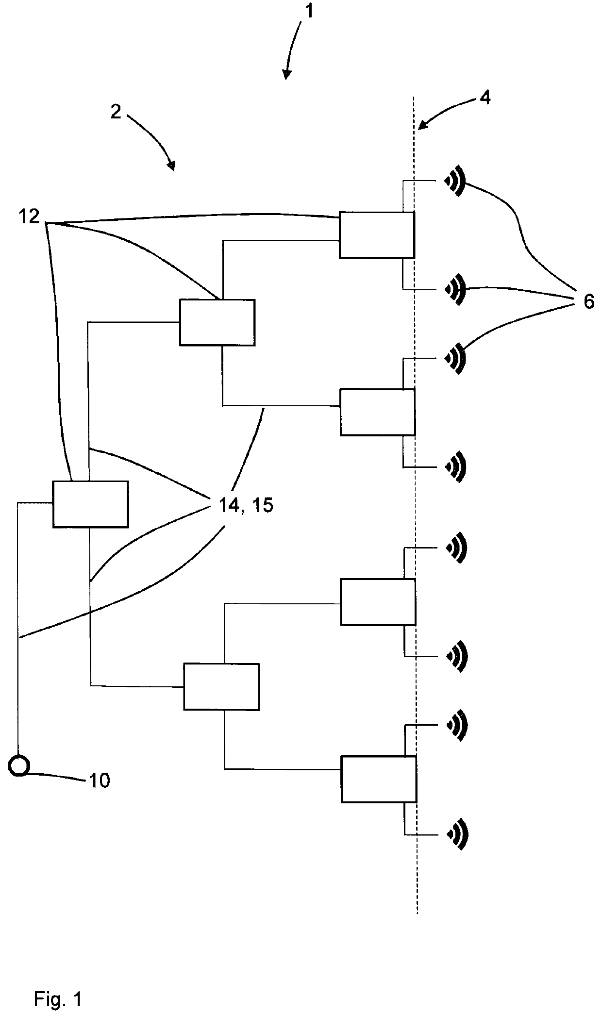
[0039]FIG. 1 schematically illustrates an antenna arrangement 1 comprising an antenna feeding network 2, an electrically conductive reflector 4, which is shown schematically in FIG. 1, and a plurality of radiating elements 6. The radiating elements 6 may be dipoles.

[0040]The antenna feeding network 2 connects a coaxial connector 10 to the plurality of radiating elements 6 via a plurality of lines 14, 15, which may be coaxial lines, which are schematically illustrated in FIG. 1. The signal to / from the connector 10 is split / combined using, in this example, three stages of splitters / combiners 12.

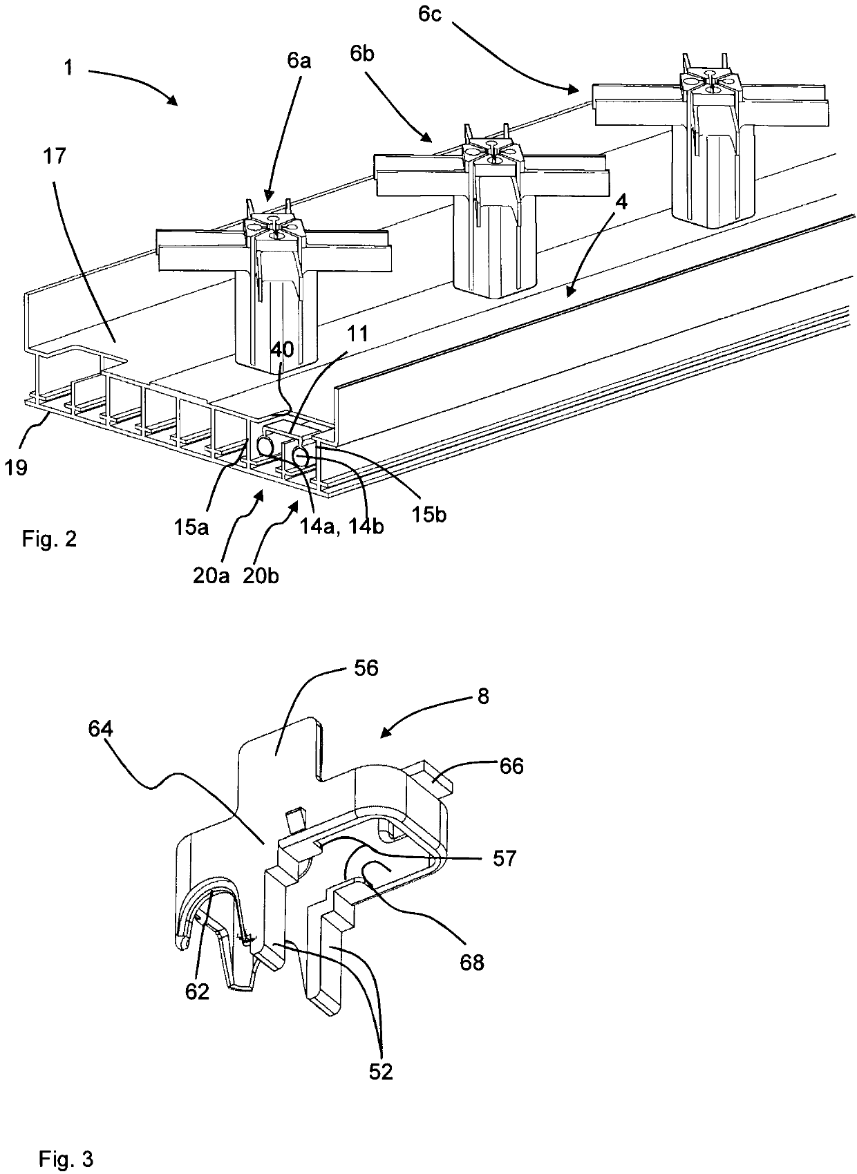
[0041]Turning now to FIG. 2, which illustrates a multi-radiator antenna 1 in a perspective view, the antenna 1 comprises the electrically conductive reflector 4 and radiating elements 6a-c.

[0042]The electrically conductive reflector 4 comprises a front side 17, where the radiating elements 6a-c are mounted and a back side 19.

[0043]FIG. 2 shows a first coaxial line 20a which comprises a first c...


PUM


Abstract

An antenna feeding network for a multi radiator antenna is provided. The antenna feeding network comprises at least one coaxial line. Each coaxial line comprises a central inner conductor and an elongated outer conductor surrounding the central inner conductor, wherein at least one of the outer conductors of the coaxial lines is provided with an opening, wherein the antenna feeding network further comprises at least one nonconductive holding element configured to be placed in the opening. The holding element is configured to hold at least one of the inner conductors in position. The invention further relates to a multi radiator antenna comprising such an antenna feeding network, and to a method for providing an electrical connection in such an antenna feeding network.

Description

TECHNICAL FIELD[0001]The invention relates to the field of antenna feeding networks for multi-radiator antennas, which feeding network comprises at least two coaxial lines.BACKGROUND OF THE INVENTION[0002]Multi-radiator antennas are frequently used in for example cellular networks. Such multi-radiator antennas comprise a number of radiating antenna elements for example in the form of dipoles for sending or receiving signals, an antenna feeding network and an electrically conductive reflector. The antenna feeding network distributes the signal from a common coaxial connector to the radiators when the antenna is transmitting and combines the signals from the radiators and feeds them to the coaxial connector when receiving. A possible implementation of such a feeding network is shown in FIG. 1.[0003]In such a network, if the splitters / combiners consist of just one junction between 3 different 50 ohm lines, impedance match would not be maintained, and the impedance seen from each port w...

Claims


Application Information

Patent Timeline
Patent Type & Authority Patents(United States)
IPC IPC(8): H01Q21/08H01Q3/32H01Q21/26H01Q1/24H01P5/02H01P3/06H01Q15/14H01R9/05H01Q21/00
CPCH01Q21/08H01P5/026H01Q3/32H01P3/06H01Q21/0006H01Q21/26H01Q1/246H01Q15/14H01R2201/02H01R9/0503H01P1/183H01P5/183H01Q3/30H01Q21/0025H01R9/16H01R24/38
Inventor YMAN, NICLAS J.JONSSON, STEFANKARLSSON, DANNORDSTRÖM, ANDREAS
Owner CELLMAX TECH AB
Why Eureka
Try Eureka