Check patentability & draft patents in minutes with Patsnap Eureka AI!

Ink jetting method and device

An inkjet and inkjet print head technology, applied in printing and other directions, can solve problems such as expensive, increased printing device cost, and increased print head cost.

Inactive Publication Date: 2002-05-29
HEWLETT PACKARD DEV CO LP
View PDF0 Cites 9 Cited by
  • Summary
  • Abstract
  • Description
  • Claims
  • Application Information

AI Technical Summary

Problems solved by technology

For fabricators, print heads formed with CMOS technology are more expensive than print heads with NMOS technology
The CMOS fabrication method is more complex than the NMOS fabrication method and requires more masking steps, thus increasing the cost of the print head
In addition, the requirement that the printing unit must provide a constant power supply to the printhead also increases the cost of the printing unit

Method used


Image

  • Ink jetting method and device
  • Ink jetting method and device
  • Ink jetting method and device

Examples


Embodiment Construction

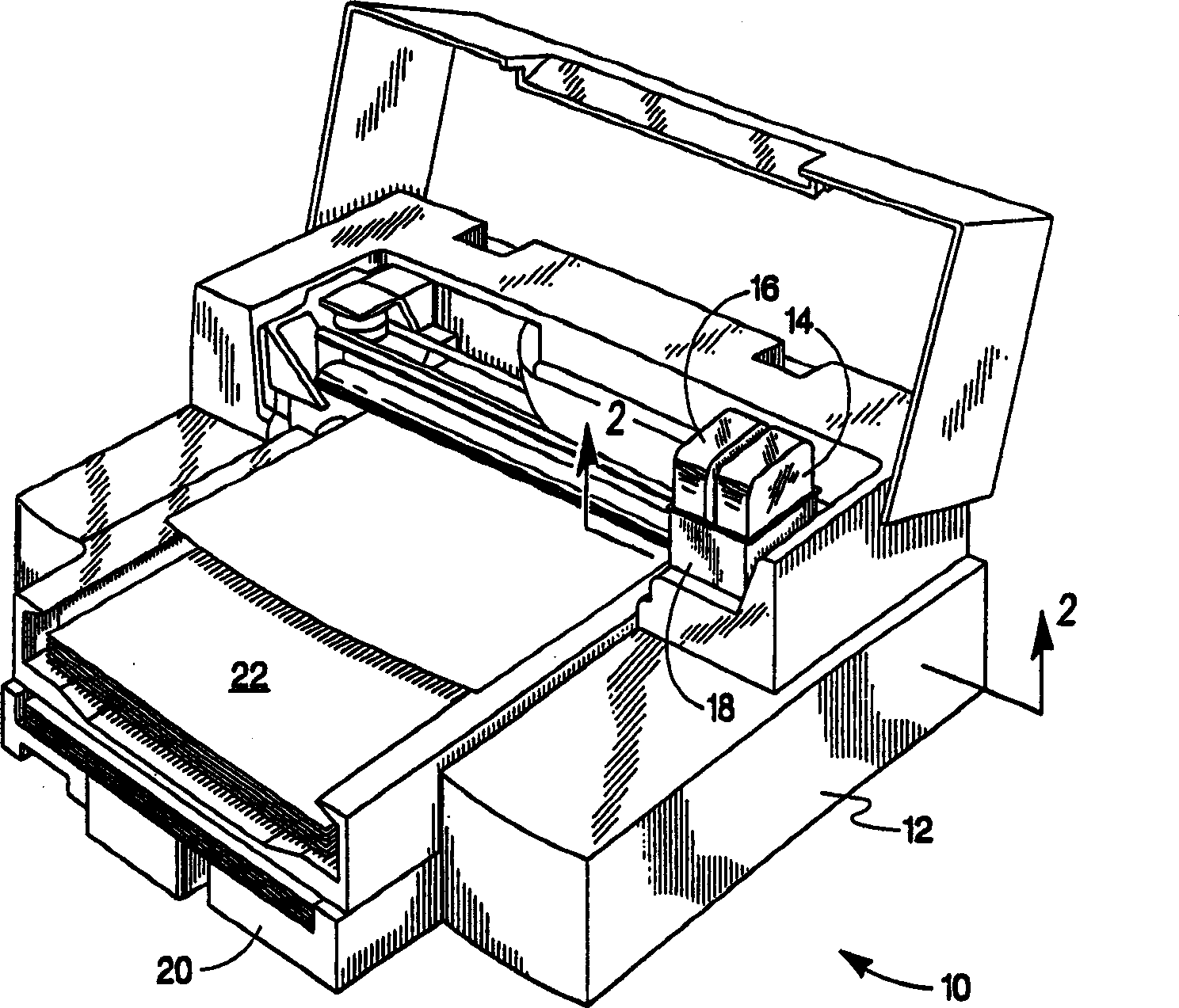
[0023] figure 1 is a perspective view of one embodiment of the inkjet printing system 10 of the present invention with the housing open. Inkjet printing system 10 includes a printer portion 12 having at least one print cartridge 14 and 16 mounted on a scanning carriage 18 . Printing section 12 includes a media cassette 20 for receiving media 22 . Scanning carriage 18 moves print cartridges 14 and 16 across print medium 22 as print medium 22 is advanced in the print zone. Printer portion 12 selectively actuates ink drop generators associated with print cartridges 14 and 16 in a printhead portion (not shown) to deposit ink on a print medium for printing.

[0024] An important aspect of the present invention pertains to the method by which printer portion 12 communicates drop generator drive information to print cartridges 14 and 16 . The drop generator drive information is used by the printhead section to drive the drop generators as the print cartridges 14 and 16 move relati...


PUM


Abstract

The present relates to an inkjet printhead having a plurality of drop generators responsive to drive current and address signals for dispensing ink. The inkjet printhead includes first and second drop generators disposed on the printhead with each of the first and second drop generators configured to receive drive current from a drive current source. Each of the first and second drop generators is configured to receive address signals from a common address source. The inkjet printhead further includes a switching device connected between the common address source and each of the first and second drop generators. The switching device is responsive to enable signals for selectively providing the address signal to only one of the first and second drop generators.

Description

technical field [0001] The present invention relates to ink jet printing devices, and more particularly to printing devices having a printhead portion for receiving ink drop drive signals to facilitate selective ejection of inks. Background technique [0002] Inkjet printing systems frequently use printheads mounted on a carriage that reciprocates across a print medium, such as paper. As the printhead moves across the print medium, the control selectively actuates each of the plurality of drop generators within the printhead to eject or deposit ink drops onto the print medium to form images and text characters. The numerous drop generators are replenished with ink provided by an ink source carried by or remote from the printhead. [0003] Individual drop generators are selectively actuated using drive signals provided by the printing system to the printheads. In thermal inkjet printing, each drop generator is driven by a current flowing through a resistive element, such as...

Claims


Application Information

Patent Timeline
Patent Type & Authority Applications(China)
IPC IPC(8): B41J2/045B41J2/05B41J2/055B41J2/06B41J2/14
CPCB41J2/04541B41J2/0458B41J2/14016B41J2/04543B41J2/04525B41J2/0455B41J2/04588B41J2/04518B41J2/06
Inventor J·M·托格尔森B·考格D·M·胡尔斯特M·H·麦肯兹
Owner HEWLETT PACKARD DEV CO LP
Features
  • R&D
  • Intellectual Property
  • Life Sciences
  • Materials
  • Tech Scout
  • Unparalleled Data Quality
  • Higher Quality Content
  • 60% Fewer Hallucinations
Learn More