
Image processing method of remote image monitoring system based on IP network and its equipment

An IP network and remote image technology, which is applied in the field of image processing, can solve problems such as unclear images, affecting display visual effects, image jaggedness, etc., and achieve the effect of flexible function organization, good display effect, and low cost

Inactive Publication Date: 2002-06-19
EMERSON NETWORK POWER CO LTD
View PDF0 Cites 3 Cited by
  • Summary
  • Abstract
  • Description
  • Claims
  • Application Information

AI Technical Summary

Problems solved by technology

This method is a basic function necessary for all remote image monitoring systems based on IP networks, and it is simple to implement. * 288, the display effect on the terminal is not satisfactory
Although some other technologies can be used for image amplification, because the remote image monitoring system requires real-time playback, smooth zooming requires a lot of calculations, which may delay the playback rate and reduce the effect. It cannot be well realized with the existing technology, and image jagged phenomenon will occur, which will affect the visual effect of display; 2) The image output is performed on a dedicated monitor, and the display effect of the dedicated monitor is much better than that of the terminal, but using a dedicated monitor For image output, it is necessary to solve the problem of interface and image separation, otherwise all interfaces (including decoded images) on the joint terminal will be output together; just because of the technical defects in the above-mentioned prior art solutions (1) and (2) , Many products began to consider outputting the decoded image information to a dedicated monitor. Windows 98 was adopted to support multi-monitor technology, and a display card was inserted on the terminal, but because Windows 98 could not distinguish the Image information and interface information can only output all the information on the terminal interface, which still cannot solve the above difficulties, it is difficult to improve user satisfaction, and it seems quite unprofessional

Method used


Image

  • Image processing method of remote image monitoring system based on IP network and its equipment
  • Image processing method of remote image monitoring system based on IP network and its equipment
  • Image processing method of remote image monitoring system based on IP network and its equipment

Examples


Embodiment Construction

[0046] In order to realize the output of the decoded image on the dedicated monitor, and to solve the defects in the image display processing of the traditional remote image monitoring system based on the IP network, the present invention adopts a combination of software and hardware to solve the above problems, The image can be displayed on the terminal or output to a dedicated monitor, and the output information is only image information. As a specific embodiment of the method of the present invention, it is expressed as follows:

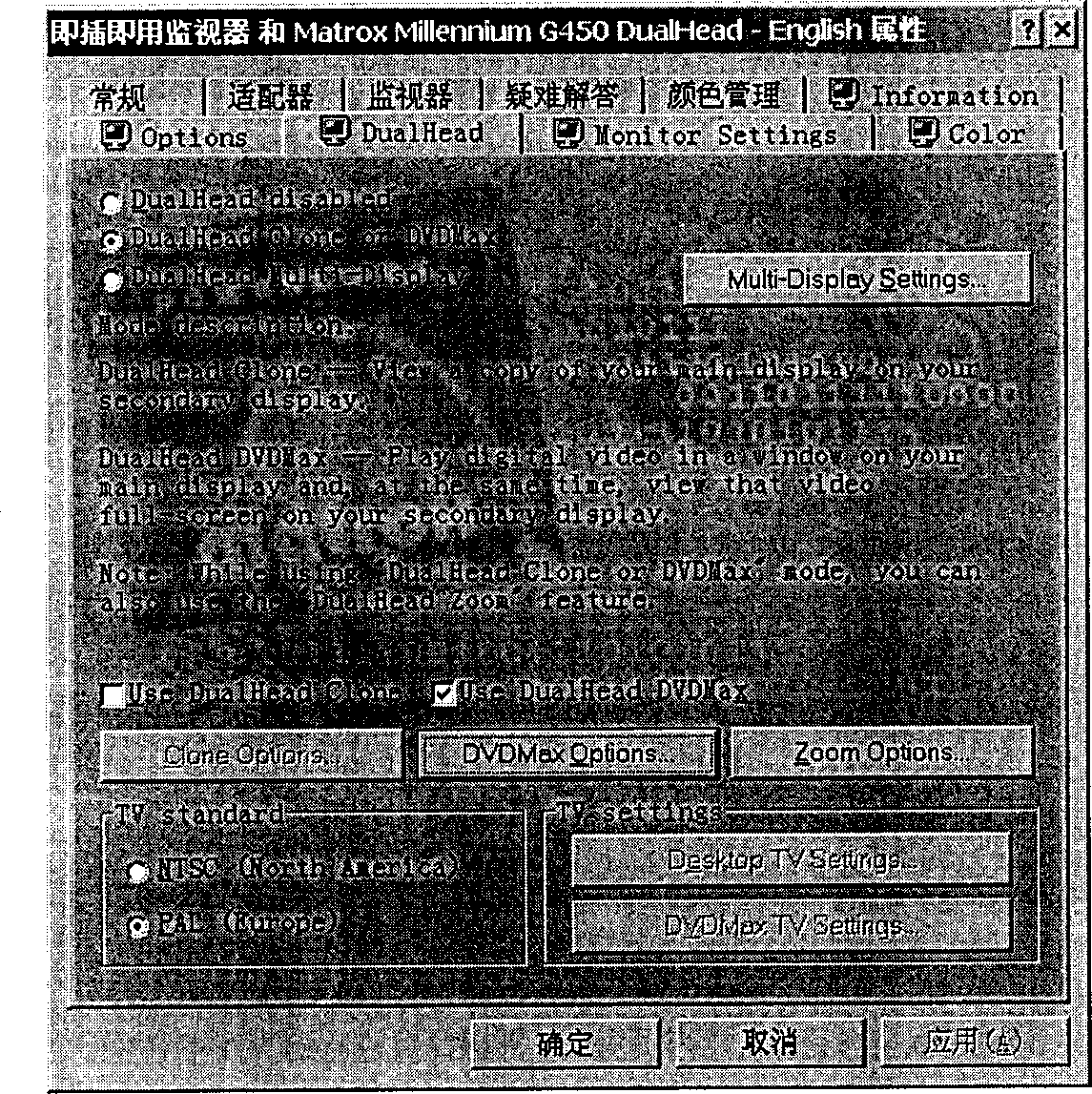
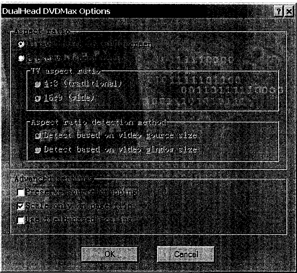
[0047] In an experimental remote video monitoring system based on IP network, such as image 3 As shown, there is a graphics workstation 301, a professional monitor 303 and a display card 302 connected therebetween. In order to realize the output of analog video (note: only output video instead of the entire Windows interface), the following methods can be used:

[0048] 1) Select Matrox G400, Matrox G450, Matrox G550 and other graphics cards th...


PUM


Abstract

The invention relates to an image processing method and equipment of remote image monitoring system that is based on IP network. With being set in working type as dual monitors and full screen, the display card supporting dual monitors is connected to a plance between monitoring terminal equipment and monitor. The displaying type of the terminal controlling equipment is set up in type of DirectX and Overlay. The image processing procedure is as follows. A remote video coded frame is decoded to a decoded video frame. Drawing the decoded video frames creates the covered surface. Covering the main surface draws the video frame, closing the covered surface. The remote video information received from IP network can be displayed on terminal as well as special monitor. The invented method is capable of providing full screen of display without sawtooth shape and video segmention by software. The invention possesses merits of good displaying effect.

Description

technical field [0001] The invention relates to image processing technology, in particular to an image processing method and equipment in an IP network-based remote image monitoring system. Background technique [0002] In the prior art, computer monitoring systems based on IP transmission have been widely used. Among them, in the remote image monitoring system based on IP networks, there are roughly two types of image output processing: 1) the received or processed image It is like directly outputting the decoded image on the display screen of the computer; that is, after the monitoring terminal in the system receives the image coded data transmitted through the network, it decodes the coded data through software or hardware, and fills in the video buffer (using DirectX or call related API) to play back the decoded image data on the display terminal to achieve the purpose of remote image monitoring. This method is a basic function necessary for all remote image monitoring ...

Claims


Application Information

Patent Timeline
IPC IPC(8): G06T3/20
Inventor 刘灿
Owner EMERSON NETWORK POWER CO LTD
Learn More