Non-synchronous motor rotary inertia identification method

A moment of inertia and asynchronous motor technology, applied in the control of motor speed or torque, control of generators, motor generator control, etc., can solve problems such as overcurrent faults, difficulty in practical use, and low identification accuracy, and achieve improved The effect of high performance and precision

Inactive Publication Date: 2002-06-19
SOMER LEROY ELECTRO TECH FUZHOU CO LTD
View PDF0 Cites 29 Cited by
  • Summary
  • Abstract
  • Description
  • Claims
  • Application Information

AI Technical Summary

Problems solved by technology

Some methods identify the moment of inertia by controlling the sudden change of motor speed by using the motor motion equation, but the process current of the motor speed sudden change is very large, which is

Method used


Image

  • Non-synchronous motor rotary inertia identification method
  • Non-synchronous motor rotary inertia identification method
  • Non-synchronous motor rotary inertia identification method

Examples


Embodiment Construction

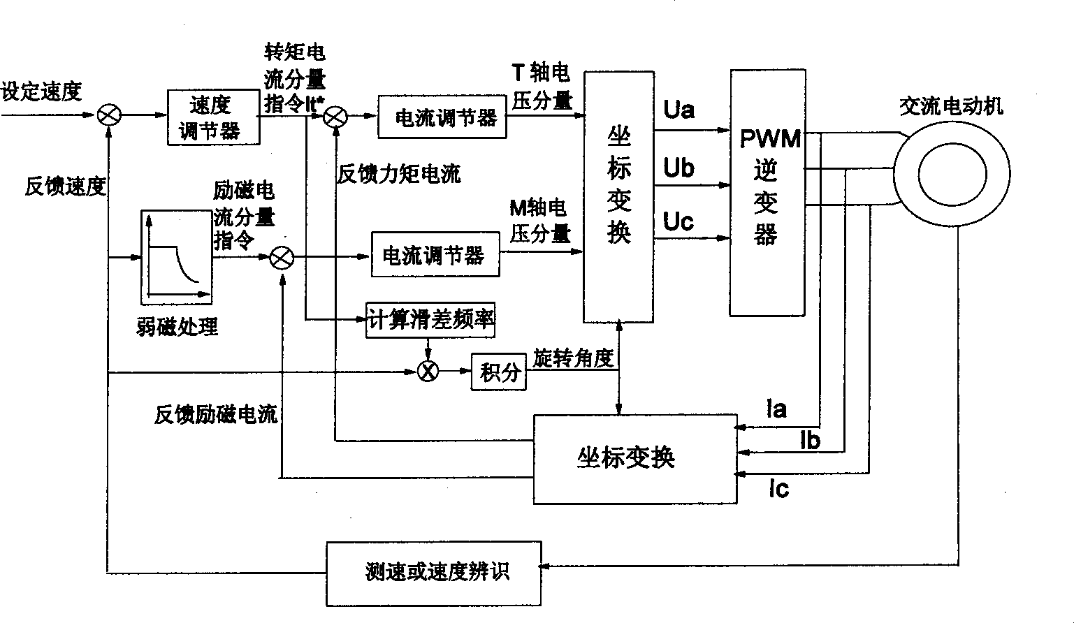
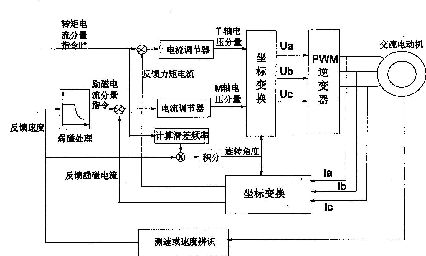
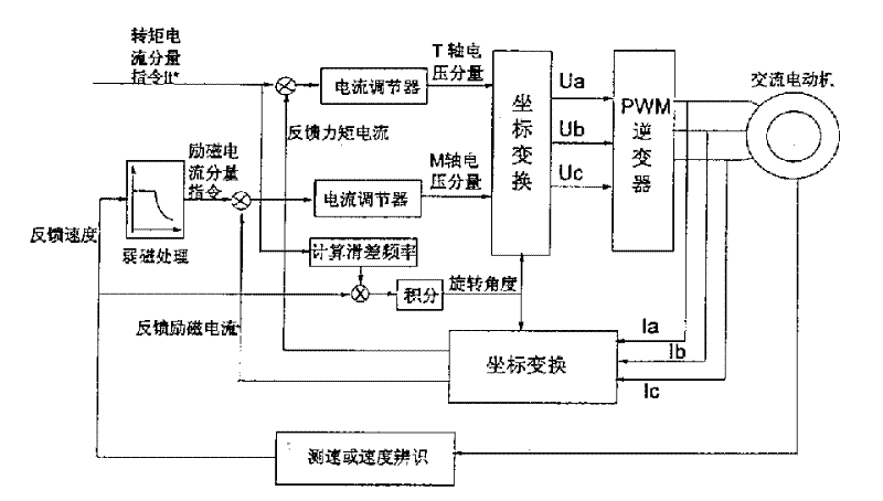
[0015] The method of the present invention utilizes the characteristics that the torque current component is easy to control in the vector control, thereby being easy to control the torque, and uses the torque vector control method to control the motor to run at a constant angular acceleration, thereby identifying the moment of inertia parameter of the motor; when calculating the moment of inertia , it is necessary to know the friction torque of the motor. The present invention utilizes the characteristic that the torque is easy to calculate in the speed vector control. Under the speed vector control, the motor is controlled to run at a certain angular speed without load, and the torque at this time can be easily obtained, that is, friction torque.

[0016] 1. Identification principle

[0017] The equation of motion of the motor is: ( 1 ) - - - J dωr dt ...


PUM


Abstract

The invention relates to a method for recognizing moment of inertia of asynchronous motor. For the purpose, following steps are taken. The electrical motor is controlled to run at constant acceleration from angular velocity omega 1 of no load operation to angular velocity omega 2 and recording the running time delta t by using control method of torque vector. By using control method of speed vector. The motor is controlled to run at constant angular velocity omega 3 of no load operation. The value of electromagnet torque is calculated based on the torque current component It at this time, so as to get the friction torque To of the motor. then based on the running time delta t and the friction torque Io, the moment of inertia Jo of the omtor is calculated. The invented method provides high accuracy for recognizing these parameters, thus improving the performance of the method of vector control.

Description

technical field [0001] The invention relates to motor technology, more specifically, relates to a method for obtaining asynchronous motor moment of inertia parameters in a vector control or direct torque control frequency conversion speed regulation system. Background technique [0002] The vector control of asynchronous motor has been widely used in the field of transmission. Its control idea is to decompose the stator current of the asynchronous motor into two parts, the excitation current component and the torque current component. The field current component is used to control the flux of the motor and the output torque is controlled by controlling the torque current component of the stator current. [0003] figure 1 It is the most widely used speed vector control system structure diagram. figure 1 The torque component command and excitation current component command of the middle stator current are the current values ​​in the synchronous rotating coordinate system, an...

Claims


Application Information

Patent Timeline
IPC IPC(8): G01M1/10H02P21/22
CPCH02P21/0035G01M1/10H02P21/22
Inventor 刘宏鑫张科孟李俊田刘国伟
Owner SOMER LEROY ELECTRO TECH FUZHOU CO LTD
Why Eureka
Try Eureka