Circular or annular coating film forming method

A coating film and circular technology, which is applied in the field of forming circular or annular coating films, can solve the problems of inability to form annular coating films and obtain uniform thickness coating films, and achieve the effect of eliminating waste

Inactive Publication Date: 2002-08-21
CHUGAI RO CO LTD
View PDF1 Cites 11 Cited by
  • Summary
  • Abstract
  • Description
  • Claims
  • Application Information

AI Technical Summary

Problems solved by technology

However, in this method, since a gap portion is formed at the center of the wafer, the thickness of the coating film increases at the bonding portion, thus causing a problem tha

Method used


Image

  • Circular or annular coating film forming method
  • Circular or annular coating film forming method
  • Circular or annular coating film forming method

Examples


Example Embodiment

[0014] An embodiment of the present invention will be described below with reference to the drawings.

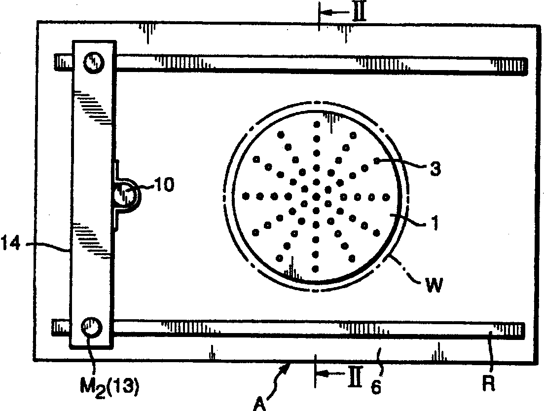
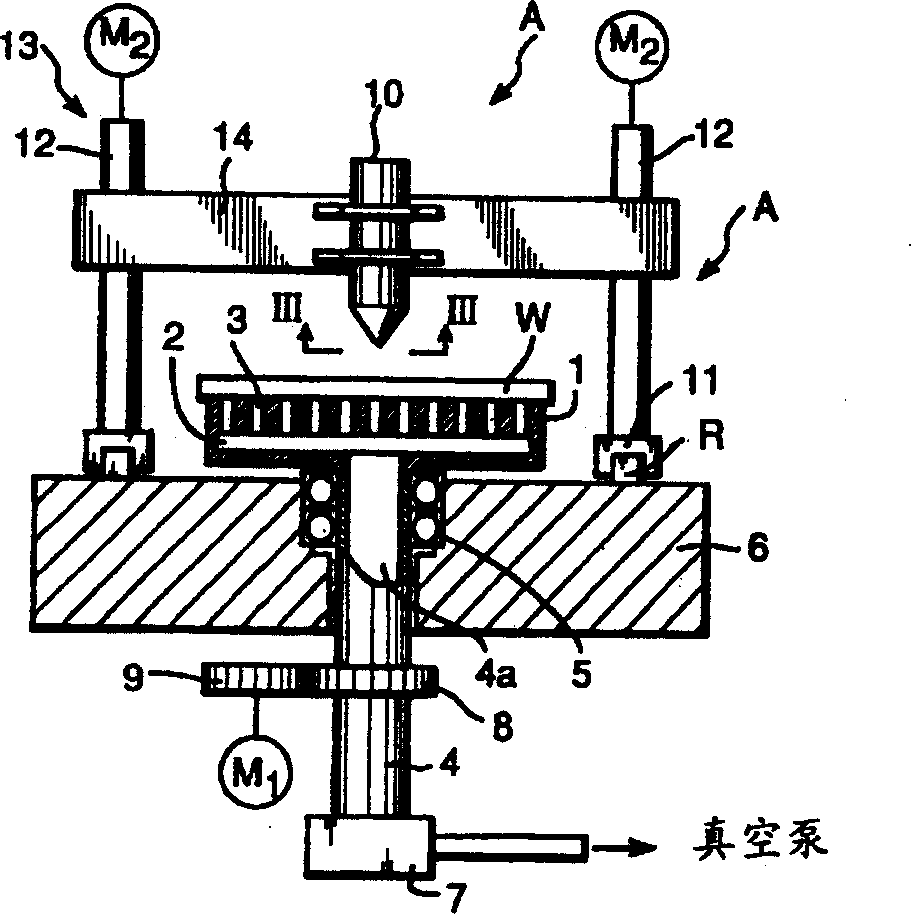
[0015] The figure shows a coating device A used to implement the present invention.

[0016] Such as figure 1 As shown, the coating device A is roughly composed of a worktable 1 and a nozzle 10. Such as figure 2 As shown, the workbench 1 is installed at one end of a hollow shaft 4 passing through the base 6, and the workbench is held by a bearing 5 provided at the penetrating part of the base 6 to rotate together with the hollow shaft 4. The other end of the hollow shaft 4 is connected to a vacuum pump not shown in the figure via a rotary joint 7. A gear 8 is provided on the protruding part of the hollow shaft 4 on the bottom surface of the base 6, using a motor M 1 To drive the gear 9 meshing with the gear 8 to rotate the table 1.

[0017] The surface of the table 1 has a predetermined flatness, for example, a flatness of 2 microns or less. A header 2 is radially provided ins...


PUM


Abstract

A method of forming a circular or annular coating film on a substrate (W) using a device of simple structure without using coating liquid wastefully, comprising the steps of, using a painting device (A) formed of a rotatable table (1) suckingly holding the substrate (W) horizontally and a horizontally movable nozzle (10) liftable relative to the table (1) and having a delivery hole (10a) at the tip part thereof, rotating the table (1) and supplying coating liquid from the delivery hole (10a) in a linear state on to the substrate (W) while moving the nozzle (10) by a specified interval between the rotating center of the table (1) and an outward specified position in one direction with the nozzle (10) held at a specified height relative to the rotating table (1) so as to form a circular or annular coating film on the substrate (W).

Description

Technical field [0001] The invention relates to a method for forming a circular or annular coating film on a substrate. Background technique [0002] Traditionally, a method such as coating with a spin coater has been considered to be a method of applying a substantially circular protective layer solution to a substantially circular wafer. However, according to this method, most of the coating liquid (about 95%) cannot be recycled and can only be discarded, resulting in extremely poor returns. [0003] In addition, a coating method using a mold coater has been proposed in Japanese Patent Publication No. 10-99764, by providing a shim (throttle plate) in a gap of the mold main body, the shim It can advance and retreat along the longitudinal direction of the gap, and continuously advance and retreat in the coating process through the shim, while moving the mold body or the wafer (substrate) horizontally, and apply the circular protective layer liquid to a wafer. [0004] In this met...

Claims


Application Information

Patent Timeline
IPC IPC(8): B05C5/02B05C11/08B05D1/00
CPCB05D1/002B05C5/0216B05C11/08
Inventor 横山卓也
Owner CHUGAI RO CO LTD
Why Eureka
Try Eureka