Drive control system for a fiber-based plasma display

a control system and plasma display technology, applied in the field of fiber-based fullcolor plasma display, can solve the problems of low efficiency, cost, short life, etc., and achieve the effects of reducing manufacturing costs, reducing capital costs, and reducing materials costs

Inactive Publication Date: 2005-09-20
MOORE CHAD BYRON
View PDF54 Cites 54 Cited by
  • Summary
  • Abstract
  • Description
  • Claims
  • Application Information

AI Technical Summary

Benefits of technology

[0025]Constructing displays using fibers has many different benefits and advantages. The economic benefits of the fiber-based plasma display technology compared to the standard plasma display technology is that fibers result in 70% lower capital costs, 50% lower manufacturing costs, and 20% lower materials costs. These lower costs are realized as a result of the manufacturing advantages. Fiber-based displays have 50% fewer process steps, no multi-level alignment steps, higher yields, simpler process steps, no large vacuum process equipment or photolithography steps, no size limit, and no shape limit. The fiber-based technology also yields performance advantages. Tight control of the fiber size and shape (intra-pixel control) along with the location of the wire electrodes leads to a fine control of the electric fields within the display. Creating the optimum electric field increases the discharge efficiency in a plasma display by a factor of two. Controlling the electric field also allows a reduction of ion bombardment on the phosphors, hence increasing the lifetime of the display. It is very easy to control the intra-pixel dimensions in a fiber plasma display; however, it is quite difficult and requires several extra steps for the standard process to achieve such control. The fiber-based technology also provides environmental advantages. Since the glass fibers can be made from a lead-free glass, there is a large reduction in the lead content of the display compared to standard plasma displays and CRTs. A completely lead-free display could even be realized if lead-free frits can be used. The innovative fiber-based technology eliminates the waste products associated with traditional photolithographic processes and the associated problems of treating the etching solution-contaminated rinse liquids. Also, there are none of the by-products from sand blasting glass. The bottom line is the fiber plasma technology is a cleaner, more environmentally safe manufacturing operation.

Problems solved by technology

Plasma display panels (PDP) have been around for about 30 years, however they have not seen widespread commercial use.
The main reasons are the short lifetime, low efficiency, and cost of the color plasma displays.
The new three electrode surface discharge structure advances many technical attributes of the display, but its complex manufacturing process and detailed structure makes manufacturing complicated and costly.
As a result, wall charges on a line as a unit are lost by the discharge caused by the erase pulse PD.
However, none of the structure forming techniques provides as many advantages as that of using fibers.

Method used


Image

  • Drive control system for a fiber-based plasma display
  • Drive control system for a fiber-based plasma display
  • Drive control system for a fiber-based plasma display

Examples


Embodiment Construction

[0072]In the following description it is understood that the such terms as “top” refers to the section or sections of a panel in a display that is closest to the viewer, whereas “bottom” refers to the section or sections of a panel in the display that is on the half away from the viewer.

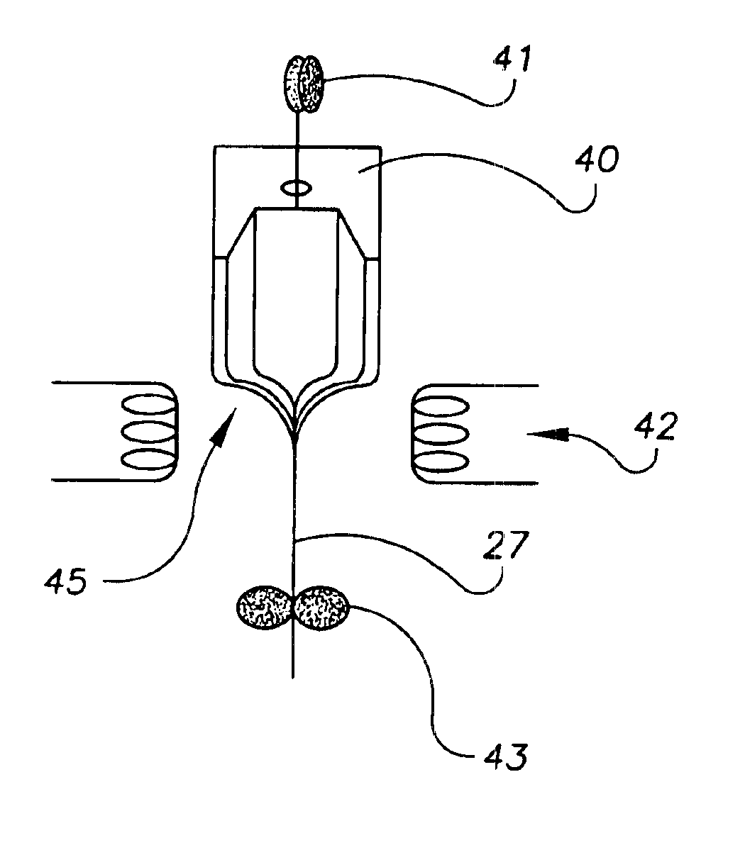
[0073]The key invention is that all structure of each row and column of the display panel is contained within each fiber of both arrays. Therefore, the entire functionality of the display is contained within each fiber of the display. Each individual fiber in the top fiber array contains all the structure of each row of the display and each individual fiber in the bottom fiber array contains all the structure of each column of the display. In the invention, glass fibers with wire electrodes are formed by drawing fiber 27 from an appropriately-shaped glass preform 40, as illustrated in FIG. 6. The fibers are assembled into arrays and placed between two glass plates to form the structure of an informat...


PUM

PropertyMeasurementUnit
pressureaaaaaaaaaa
viscosityaaaaaaaaaa
angleaaaaaaaaaa

Abstract

A full color fiber plasma display device includes two glass plates sandwiched around a top fiber array and a bottom fiber array. The top and bottom fiber arrays are substantially orthogonal and define a structure of the display, with the top fiber array disposed on a side facing towards a viewer. The top fiber array includes identical top fibers, each top fiber including two sustain electrodes located near a surface of the top fiber on a side facing away from the viewer. A thin dielectric layer separates the sustain electrodes from the plasma channel formed by a bottom fiber array. The bottom fiber array includes three alternating bottom fibers, each bottom fiber including a pair of barrier ribs that define the plasma channel, an address electrode located near a surface of the plasma channel, and a phosphor layer coating on the surface of the plasma channel, wherein a luminescent color of the phosphor coating in each of the three alternating bottom fibers represents a subpixel color of the plasma display. Each subpixel is formed by a crossing of one top fiber and one corresponding bottom fiber. The plasma display is hermetically sealed with a glass frit. The sustain and address electrodes are brought out through the glass frit for direct connection to a drive control system.

Description

REFERENCE TO RELATED APPLICATIONS[0001]This is a divisional patent application of application Ser. No. 09 / 299,370, filed Apr. 26, 1999, now U.S. Pat. No. 6,414,433, entitled “FIBER-BASED PLASMA DISPLAY”. The aforementioned application is hereby incorporated herein by reference.FIELD OF THE INVENTION[0002]The invention pertains to the field of fiber-based displays and methods of manufacture. More particularly, the invention pertains to fiber-based full-color plasma displays.BACKGROUND OF THE INVENTION[0003]All electronic display technologies are composed of a large array of display picture elements, called pixels arranged in a two-dimensional matrix. Color is added to these displays by subdividing each pixel element into three-color subpixels. The electronic display technologies can be further divided into a category known as flat-panel displays. The basic structure of a flat-panel display comprises two glass plates with a conductor pattern of electrodes on the inner surfaces of each...

Claims


Application Information

Patent Timeline
Patent Type & Authority Patents(United States)
IPC IPC(8): C03B37/16C03B37/03C03B37/026C03B37/025C03B37/10C03B37/14C03C17/00C03B37/15C03B37/02C03C27/06G02F1/13G02F1/133G09G3/36G09G3/28H01J9/24H01J17/16H01J17/02H01J11/00
CPCC03B37/025C03B37/026C03B37/03C03B37/14C03B37/15C03B37/16C03C17/007C03C27/06G02F1/13334H01J9/241H01J11/00H01J2211/36H01J2211/38
Inventor MOORE, CHAD BYRON
Owner MOORE CHAD BYRON
Why Eureka
Try Eureka