Rapid densification of porous bodies (preforms) with high viscosity resins or pitches using a resin transfer molding process

Inactive Publication Date: 2007-02-06
HONEYWELL INT INC
View PDF14 Cites 54 Cited by
  • Summary
  • Abstract
  • Description
  • Claims
  • Application Information

AI Technical Summary

Benefits of technology

[0032]The present invention, in part, also provides a hydraulic press to constrain a mold containing the porous preform or rigid porous body.
[0033]The present invention, in part, also provides a mold which efficiently distributes the resin uniformly throughout the preform.
[0034]The present invention, in part, provides for a mold that may be oriented horizontally within the press. A gate, having a nozzle, can be disposed in the center of a face of a mold half. The mold can have tapered cavities to promote adequate molten resin flow.
[0035]The present invention, in part, also pertains to a resin transfer molding process that comprises: placing a porous preform into a mold; injecting a molten resin or pitch into the mold; allowing the resin or pitch to cool below the melting point; and removing the impregnated preform from the mold, wherein the mold comprises a top half; a bottom half opposed to the top half so that the top half and the bottom half form a mold cavity; at least one gate disposed in the top half or the bottom half; a valve that can admit resin into the gate; and an arrangement for providing venting and/or vacuum to the mold.
[0036]The porous body can be a fibrous preform, a carbon or ceramic fiber preform, a nonwoven preform, a rigidized fibrous preform, a porous carbon or ceramic body, or a foam preform or a rigidized foam preform. The preform can be carbonized or graphitized. The preform can be infiltrated

Problems solved by technology

The CVD/CVI process is highly capital intensive and suffers from long cycle times with multiple densification cycles typically taking several weeks to complete.
The VPI process is limited to using resin and pitches that possess low viscosity and associated low carbon yields.
Therefore, densification of porous preforms with liquid resin and pitch precursors using the VPI process typically requires several cycles of impregnation followed by carbonization (frequently up to 7 cycles) and require long cycle times up to several weeks to achieve the desired final density.
However, the high-pressure vessels are capital intensive and of limited size thereby limiting the number of preforms densified in one vessel.
The high pressures used also increase the risk of explosion and special safety precautions are required to meet safety standards.
However, there are many problems associated with using these high char yield resins in the current VPI processes related to their higher viscosity and associated higher process temperatures.
In fact, RTM was originally introduced in the mid 1940s but met with little commercial success until the

Method used


Image

  • Rapid densification of porous bodies (preforms) with high viscosity resins or pitches using a resin transfer molding process
  • Rapid densification of porous bodies (preforms) with high viscosity resins or pitches using a resin transfer molding process
  • Rapid densification of porous bodies (preforms) with high viscosity resins or pitches using a resin transfer molding process

Examples


Example

EXAMPLE 1

[0070]A 35:1 length to diameter ratio Killion extruder with 5 heating zones along the barrel was coupled directly to a heated aluminum mold. The Extruder temperature profile was as follows:[0071]Feed section=240° C. (464° F.) Zone 1[0072]278° C. (532° F.) Zone 2[0073]310° C. (590° F.) Zone 3[0074]305° C. (581° F.) Zone 4[0075]300° C. (572° F.) Zone 5[0076]305° C. (581° F.) Die Zone[0077]300° C. (572° F.) Mold

The fibrous preform was pre-heated in the mold for 2 hours until an internal temperature of 285° C. (545° F.) was reached prior to infiltration. The extruder screw was initially run at 20 rpm and reduced to 15 rpm during the run. The AR pitch resin was introduced into the extruder via a hopper and extruded into the porous fiber preform over a 2 hour period at 800–900 psi (5.52–6.21 MPa) melt pressure. The actual resin melt temperature was measured using a thermocouple located in the melt stream. The melt temperature during the infiltration was 318° C.–321° C. (604–610° ...

Example

EXAMPLE 2

[0084]A non-woven porous preform was carbonized and exposed to one cycle CVD densification to rigidize the part prior to being infiltrated with resin.

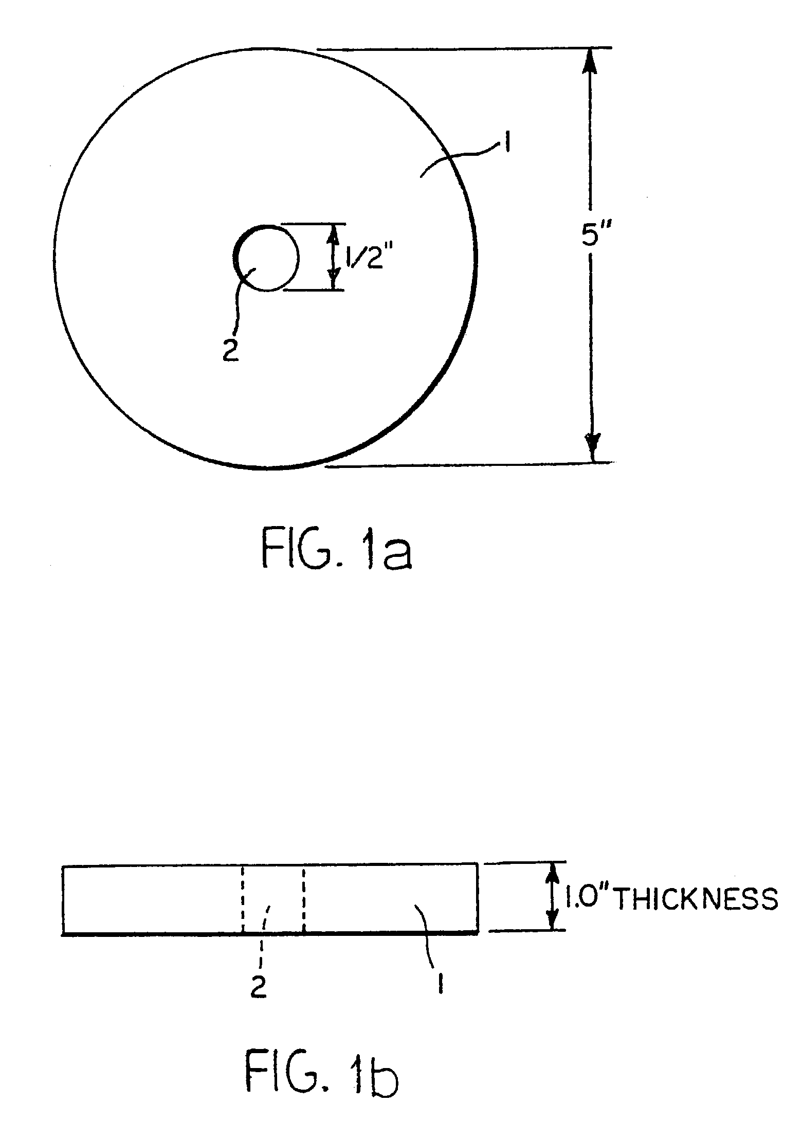
[0085]The Killion extruder / mold system as described in Example 1 was used. A CVD rigidized fibrous pre-form 5 inches (12.7 cm) in diameter, 1 inch (2.54 cm) thick with a 0.5 inch (1.27 cm) hole drilled in the center was cut from a full size aircraft brake disc preform (Refer to FIGS. 1 and 2). The aluminum mold was 6 inches (15.24 cm) in diameter and 1 inch (2.54 cm) thick equipped with a 0.052 inch (1.32 mm) vent opening. The larger vent opening was used to improve the venting of resin (AR pitch) from the mold while keeping the extruder operating throughout the entire infiltration process. The objective was to keep the screw turning, maintain a constant pressure, provide a melt seal along the screw and reduce the overall run time from 2 hours to 15 minutes. The extruder settings are described below:[0086]Feed section=240° C. ...

Example

EXAMPLE 3

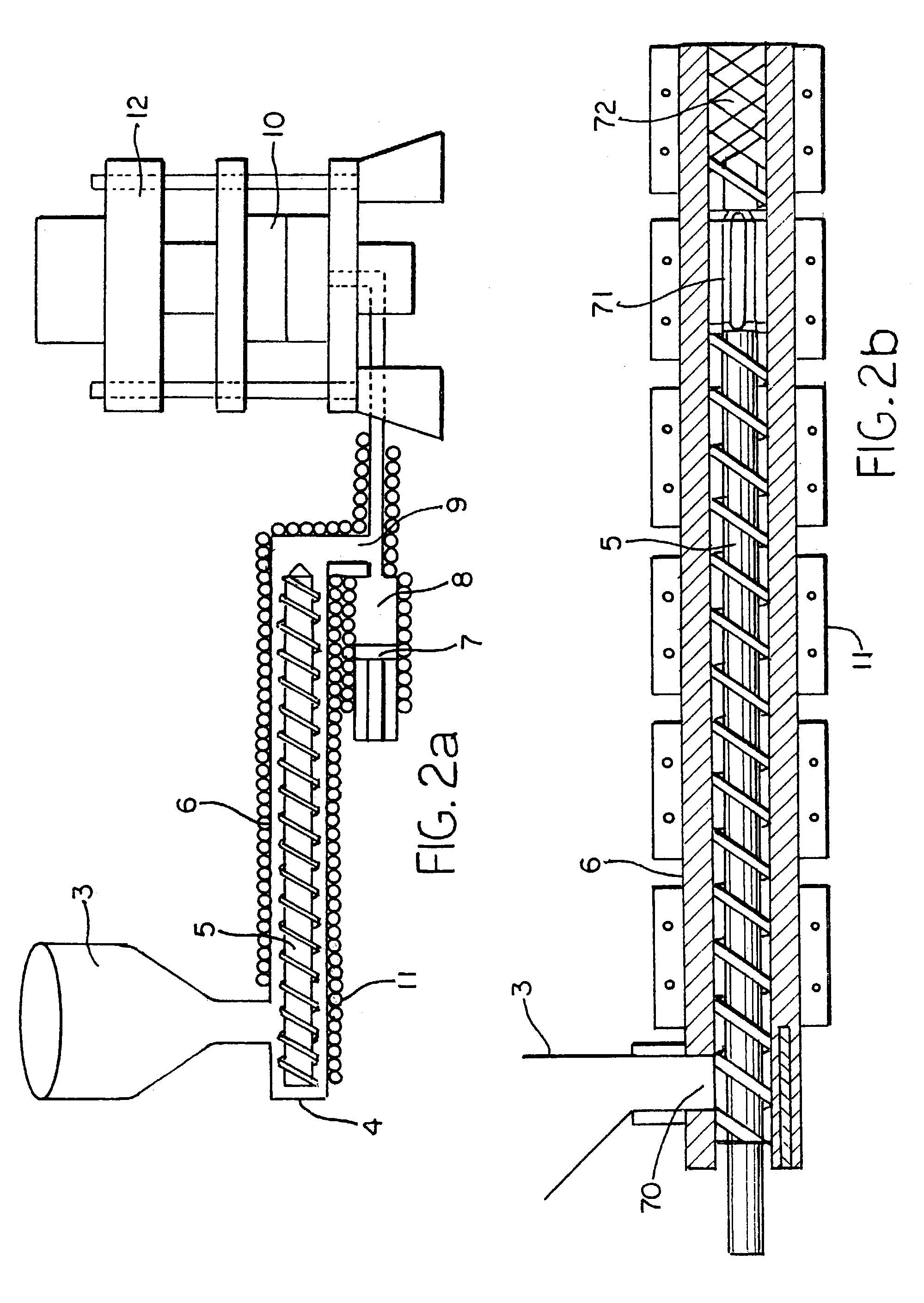
[0117]The injection molding apparatus described in FIG. 2 was used. The hydraulic press has a 500 ton clamping capability. The accumulator has a theoretical volume of 847 cubic inches (13,880 cm3), and the measured volume using resin is about 830 cubic inches (13,601 cm3). When completely filled with AR pitch resin, the accumulator contains approximately 37 lb. (16.8 kg) of resin. Temperatures in the extruder can be measured at 6 locations in the extruder barrel, the extruder head, the flow adapter, the accumulator head, the accumulator, the dump valve, the dump pipe, the melt pipe, the nozzle block, the nozzle extension and the feed throat. Heat is supplied to the extruder by an electrical heater and the mold is heated by hot oil circulation. The extruder screw creates pressure within the resin melt, and the pressure is maintained in the accumulator.

[0118]The part was preheated to 707° F. (350° C.) in an oven and transferred into the mold cavity just prior to infiltration....


PUM

PropertyMeasurementUnit
Lengthaaaaaaaaaa
Temperatureaaaaaaaaaa

Abstract

A resin transfer molding (RTM) process is disclosed for rapidly filling a fibrous preform and/or a rigid, porous body with high viscosity resin or pitch. The process is suitable for impregnated multiple porous bodies stacked in a single mold. The process uses a fibrous preform or rigid porous body which is placed into a mold matching the desired part geometry. A resin is injected into the mold at temperature and pressure. After cooling, the infiltrated component is removed from the mold. The mold is constructed from two halves fitted to form at least one mold cavity. A gate fitted with a nozzle is set into one of the mold halves, and a valve admits resin or pitch into the gate area. Venting or vacuum can be applied to the mold. The mold is held in a hydraulic press and an extruder, optionally fitted with an accumulator, supplies molten resin or pitch to the mold.

Description

CROSS REFERENCE TO RELATED APPLICATION[0001]This application is a divisional of application Ser. No. 09 / 653,880 filed Sep. 1, 2000 now U.S. Pat. No. 6,537,470, the entire contents of which is hereby expressly incorporated by reference.TECHNICAL FIELD AND INDUSTRIAL APPLICABILITY OF THE INVENTION[0002]The invention is directed toward an improved process to rapidly densify high temperature materials including carbon-carbon (“C—C”) composites and porous preforms with a high viscosity resin or pitch using resin transfer molding techniques.BACKGROUND OF THE INVENTION[0003]The present invention describes an improved process for the rapid densification of high temperature materials including C—C composites, carbon and ceramic fiber reinforced preforms as well as carbon and ceramic foams.[0004]Typically, these high temperature materials are densified using CVD / CVI (Chemical Vapor Deposition / Chemical Vapor Infiltration) of carbon and / or ceramic, or liquid infiltration with a resin and / or pit...

Claims


Application Information

Patent Timeline
IPC IPC(8): B29C45/00B29C39/24B29C39/02B29C70/48C04B35/83F16D69/02
CPCB29C70/48C04B35/83F16D69/023C04B35/521C04B35/522C04B35/524C04B2235/77C04B2235/6021C04B2235/6022C04B2235/614C04B2235/616B29C45/14
Inventor WOOD, MICHAEL D.DILLON, FRANKHECKELSBERG, RICHARD A.HOLLOWAY, ROGER W.LAFOREST, MARK L.MURDIE, NEILPARKER, CHARLES A.PIGFORD, JAMES F.
Owner HONEYWELL INT INC
Why Eureka
Try Eureka