
Vehicle conveyer

A technology for conveying devices and vehicles, which is applied to railway vehicles, transportation and packaging, conveyors, etc., and can solve problems such as increasing costs

Inactive Publication Date: 2002-09-25
DAIFUKU CO LTD
View PDF0 Cites 30 Cited by
  • Summary
  • Abstract
  • Description
  • Claims
  • Application Information

AI Technical Summary

Problems solved by technology

This greatly increases the cost of the equipment used to steer the vehicle

Method used


Image

  • Vehicle conveyer
  • Vehicle conveyer
  • Vehicle conveyer

Examples


Embodiment Construction

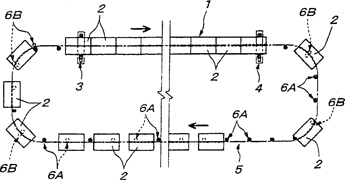
[0022] see Figure 1A , the main running line 1 of an assembly process is a linear running line. The rear (starting) end of the running line 1 is equipped with a transmission device 3 as the main driving force for pushing the vehicle 2 forward. The front end of the running line 1 is equipped with a braking device 4 that prevents the vehicle 2 from running at a speed higher than a predetermined speed. A secondary running line 5 can continue to make the vehicle 2 return from the front end of the main running line 1 to the rear end. The auxiliary running line 5 is equipped with a plurality of transmission devices 6A and 6B as auxiliary driving force at intervals smaller than the entire length of the vehicle 2 . These transmissions 6A and 6B each push the vehicles 2 forward one by one at high speed.

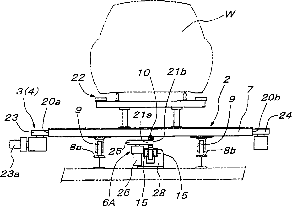
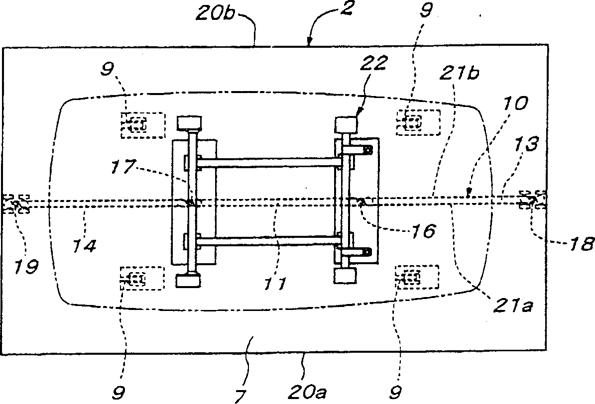
[0023] Such as Figure 1B , 2 As shown in and 3, each vehicle 2 includes a rectangular vehicle floor 7 that is longer in the vehicle running direction. A pair of front freewheel...


PUM


Abstract

The vehicle delivery device of the present invention includes a plurality of vehicles and a vehicle running line. Each vehicle includes: a vehicle floor having a main transmission friction surface, the friction surface being a side formed on or close to at least one of the left and right sides of the vehicle floor, which is parallel to the direction of travel of the vehicle; A rod extending along the centerline of the vehicle floor, the centerline being parallel to the direction of travel, the rod has a side forming a friction surface for an auxiliary drive. The running line includes a main conveyor line as a linear conveyor line or an auxiliary conveyor line. The main conveyor line is equipped with a transmission device used as a main driving force. drive wheel. The auxiliary conveying line is equipped with a plurality of transmission devices used as auxiliary driving force, and each transmission device includes a friction drive wheel for pressure contact with the friction surface of the vehicle. The transmissions are arranged at intervals in the direction of travel.

Description

(1) Technical field [0001] The invention relates to a vehicle transport device. (2) Background technology [0002] Vehicle conveyors of this type include a linear running line for vehicles used as a means of constant speed continuous transport during the assembly of automobiles or the like. Each vehicle includes a floor having a pair of sides parallel to the direction of travel of the vehicle. The transmission that propels the vehicle on a linear running line consists of friction surfaces that act as a drive and friction drive wheels that act as the vehicle's propulsion. The friction surface is the side of the vehicle floor. A drive wheel is positioned at the rear (beginning) end of the conveyor line and engages the friction surface in a pressure manner. Each vehicle pushes a vehicle ahead. [0003] The vehicle transport apparatus also includes a return travel line for returning the vehicle from the front end of the linear travel line to the rear end thereof. The front ...

Claims


Application Information

Patent Timeline
IPC IPC(8): B61B13/06B61B13/00B62D65/18B65G35/06
CPCB62D65/18B65G35/06B61B13/00
Inventor 增垣满雄铃木孝晴
Owner DAIFUKU CO LTD
Learn More