Self-tracking filter

A filter and self-tracking technology, applied in impedance networks, digital technology networks, electrical components, etc., can solve problems such as inaccurate zero-crossing detection, inaccurate counting of track crossings, and missed zero-crossings

Inactive Publication Date: 2002-10-02
KONINKLIJKE PHILIPS ELECTRONICS NV
View PDF0 Cites 4 Cited by
  • Summary
  • Abstract
  • Description
  • Claims
  • Application Information

AI Technical Summary

Problems solved by technology

[0008] Although methods for detecting track crossings using detection of zero crossings and error signals are known, such as German patent 40.29. is the detection of inaccurate zero crossings, which in turn will cause inaccurate counts of trace crossings

Method used


Image

  • Self-tracking filter
  • Self-tracking filter
  • Self-tracking filter

Examples


Embodiment Construction

[0027] Embodiment of the invention

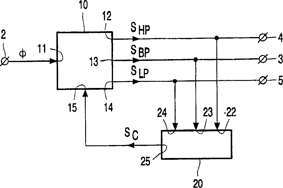
[0028] figure 1 A block diagram of a self-tracking bandpass filter 1 with a signal input 2 and a filtered signal output 3 according to the invention is schematically shown. A self-tracking band-pass filter 1 consists of a high-pass signal S HP , bandpass signal S BP and low-pass signal S LP A high-pass output 12, a band-pass output 13, and a low-pass output 14 of a controllable filter 10. The controllable filter 10 also comprises a signal input 11 coupled to the signal input 2 of the self-tracking bandpass filter 1 for receiving the signal φ to be filtered, and a control input 15 for receiving the control signal Sc. The self-tracking bandpass filter 1 also includes a control unit 20 whose signal inputs 22, 23, 24 receive the above-mentioned output signal S from the controllable filter 10 respectively. HP , S BP and S LP And on the basis of these received signals a control signal Sc for controlling the controllable filter 10 is genera...


PUM


Abstract

A self-tracking bandpass filter (1) comprising a controllable filter (10), the controllable filter (10) having a signal input (11) for receiving a signal (φ) to be filtered, for providing a bandpass output of a bandpass signal (SBP) at a center frequency (f0), and a control input (15) for receiving a control signal (SC); and a control input (15) coupled to a controllable filter (10) A control unit (20) for generating such a control signal (SC) that the center frequency (fO) of the bandpass characteristic (HB) of the controllable filter (10) is substantially equal to that of the input signal (φ) frequency (f).

Description

field of invention [0001] The present invention generally relates to a filter circuit. Background technique [0002] It is often technically necessary to filter various signals. Especially when a signal includes a main frequency component and an interfering frequency component whose frequency is different from the main frequency component, it is necessary to filter out the interfering frequency component. If the interfering frequency components can be expected to be at both higher and lower frequency bands relative to the main frequency components, the filter used is a bandpass filter. If the dominant frequency is known in advance, those skilled in the art know how to design a bandpass filter circuit with a passband centered on the expected dominant frequency component. According to the requirements of the filter, the width of the passband can be designed to be very narrow. However, narrow passbands cannot be used if the exact dominant frequency is not known in advance, f...

Claims


Application Information

Patent Timeline
Patent Type & Authority Applications(China)
IPC IPC(8): H03H11/04
CPCH03H11/04H03H17/02H03H11/0427
Inventor J·L·巴克斯
Owner KONINKLIJKE PHILIPS ELECTRONICS NV
Why Eureka
Try Eureka