Dressing glass

A technology for vanity mirrors and mirror bases, applied in the field of vanity mirrors, can solve the problems of increasing costs and the thickness of vanity mirrors cannot be thinner, and achieve the effect of increasing production costs

Inactive Publication Date: 2002-10-16
株式会社T&T
View PDF0 Cites 2 Cited by
  • Summary
  • Abstract
  • Description
  • Claims
  • Application Information

AI Technical Summary

Problems solved by technology

Therefore, due to this limitation, no matter how hard we try, the thickness of the vanity mirror cannot be thinner
[0008] Another problem is that each fuse lamp 26 needs to be connected to the bus bar 27 through the metal part 25 that fixes the lamp, and this also increases the cost of production

Method used


Image

  • Dressing glass
  • Dressing glass
  • Dressing glass

Examples


Embodiment approach

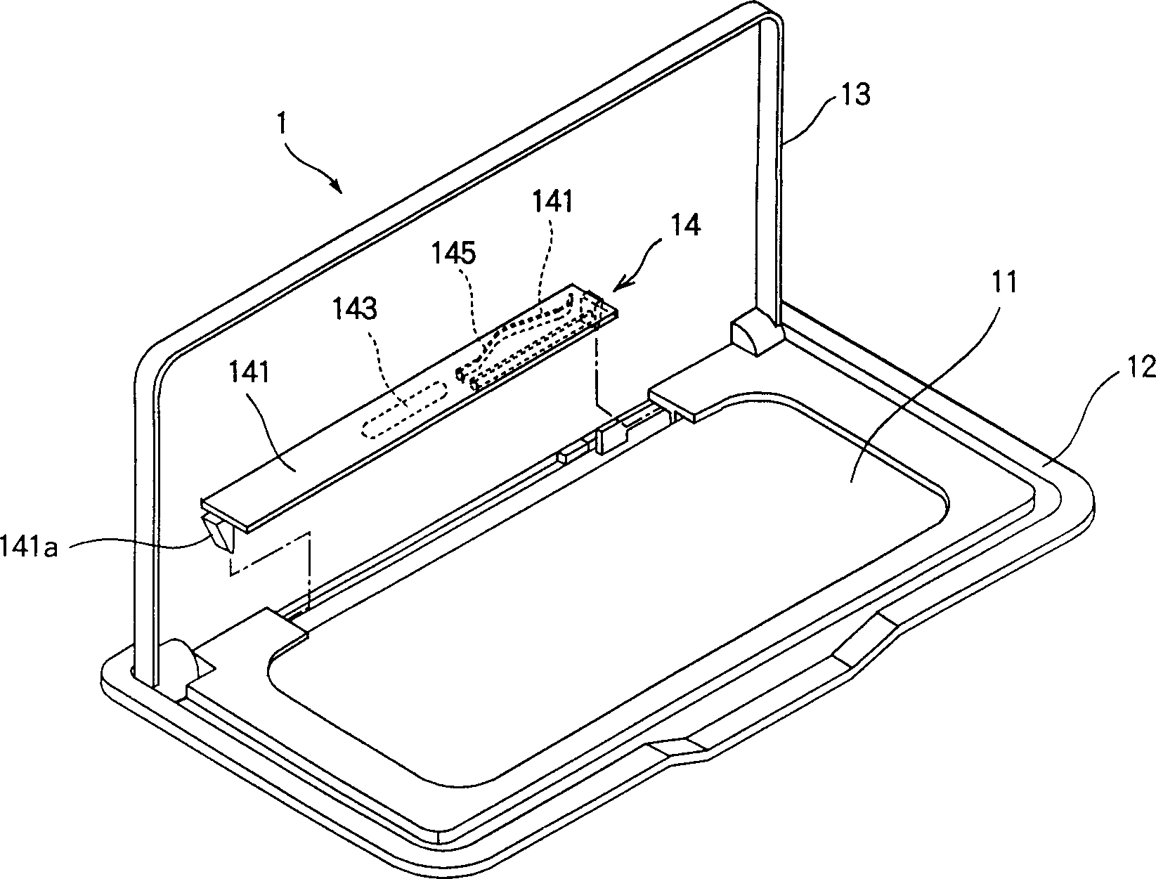
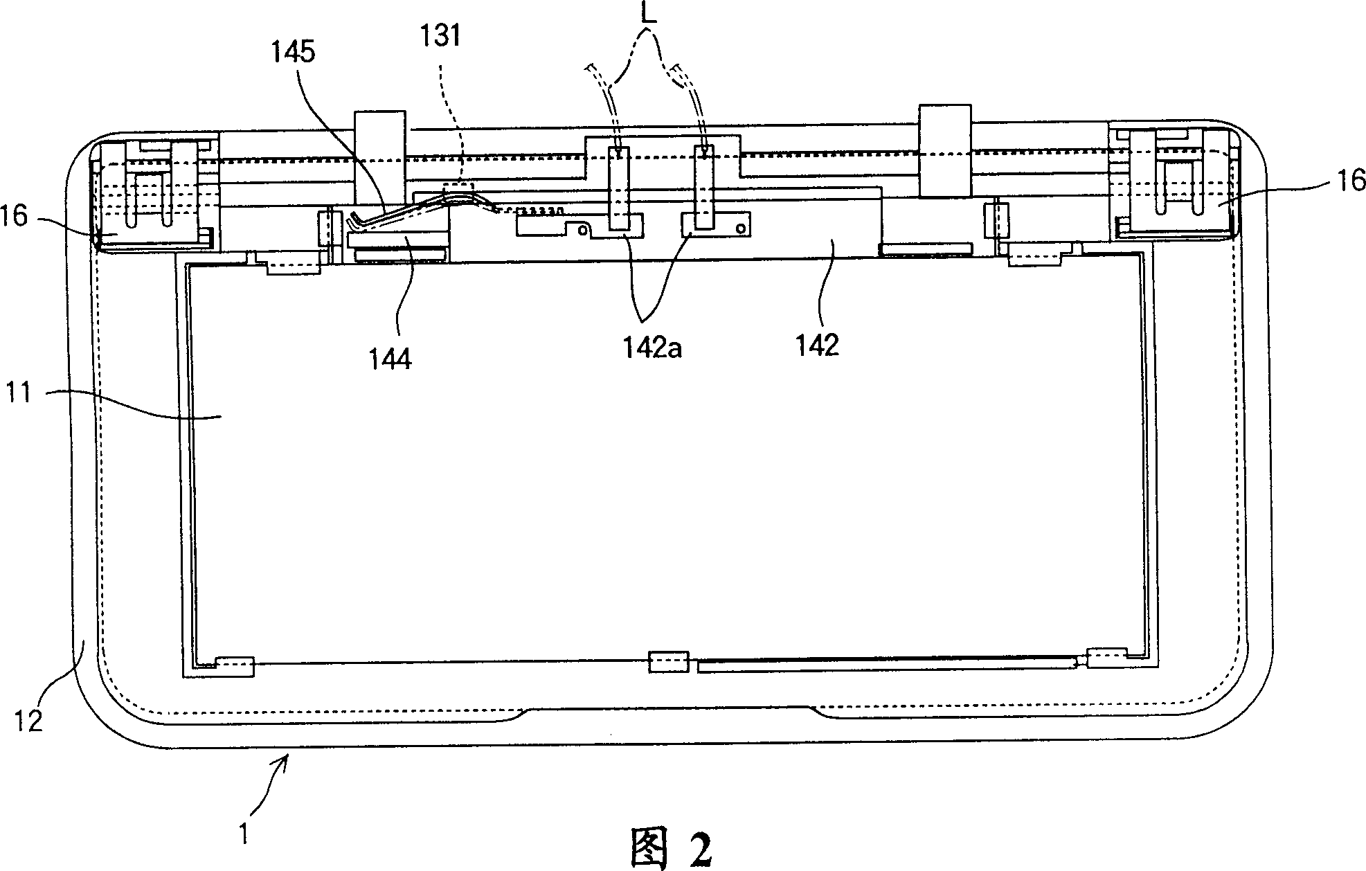
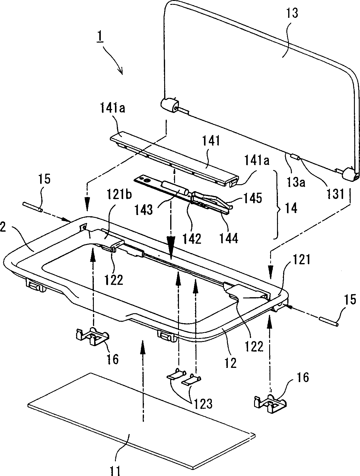
[0034] So far, the above description is given based on the embodiment, in which the base plate 142 is detachably fixed on the lens plate 141 with screws. The present invention is not limited to this embodiment. The lens plate may be provided with an engaging protrusion. The engaging protrusion can be elastically engaged with the hole in the base plate 142, so that the lens plate and the base plate are detachably connected to each other.

[0035] As explained above, this invention includes: a mirror holder mounted with a mirror; a mirror cover that is openably connected to the mirror holder through a loose leaf; and a mirror cover that is connected and disconnected by opening and closing the mirror cover The switch; a substrate on which the switch is mounted; a lighting device mounted with a lamp, the lamp is connected to the wires drawn from two opposite ends of the substrate; and a substrate that can be freely connected to the substrate Or the disassembled lens plate. Since the i...


PUM


Abstract

A vanity mirror, comprising: a mirror base installed with a mirror; a mirror cover that is openably connected to the mirror base through a hinge; a mirror cover that is connected and disconnected by opening and closing the mirror cover A switch; an illuminating device composed of a lamp connected with wires and a lens plate, the lens plate can be connected or detached from the base plate; the illuminating device is detachably connected to the mirror base.

Description

Technical field [0001] The present invention relates to an improved vanity mirror, and more specifically to a vanity mirror that uses fewer parts and is thinner. Background of the invention [0002] For the convenience of passengers, some vanity mirrors used in cars, especially those mounted on car sun visors, are usually illuminated by lights at night. [0003] Figure 7 and Figure 8 It is a common vanity mirror, where the vanity mirror marked 20 includes: a mirror base 22 with a mirror 21 installed in the center; a mirror cover 23 detachably connected to the mirror base 22 through a loose leaf, and a mirror cover 23 mounted on the back of the mirror 21 The lamp part 24 is turned on or off by the opening and closing of the mirror cover 23. [0004] In addition, the lamp portion 24 includes: recessed portions 221 on both sides of the mirror 21 in the mirror base 22; a metal fixture 25 for the lighting lamp installed from the back in the recessed portion 221 and protrusions mounte...

Claims


Application Information

Patent Timeline
Patent Type & Authority Applications(China)
IPC IPC(8): B60N3/00B60J3/02B60Q3/02
CPCB60J3/0282B60Q3/252
Inventor 冈野博文持田哲男
Owner 株式会社T&T
Why Eureka
Try Eureka