Harness frame angle connecting device

A corner connection, heald frame technology, used in healds, transportation and packaging, textiles, etc.

Inactive Publication Date: 2002-11-13
GROZ BECKERT KG
View PDF4 Cites 6 Cited by
  • Summary
  • Abstract
  • Description
  • Claims
  • Application Information

AI Technical Summary

Problems solved by technology

However, this solution is no longer suitable for new heald frames due to the completely different design of the heald frame profile

Method used


Image

  • Harness frame angle connecting device
  • Harness frame angle connecting device
  • Harness frame angle connecting device

Examples


Embodiment Construction

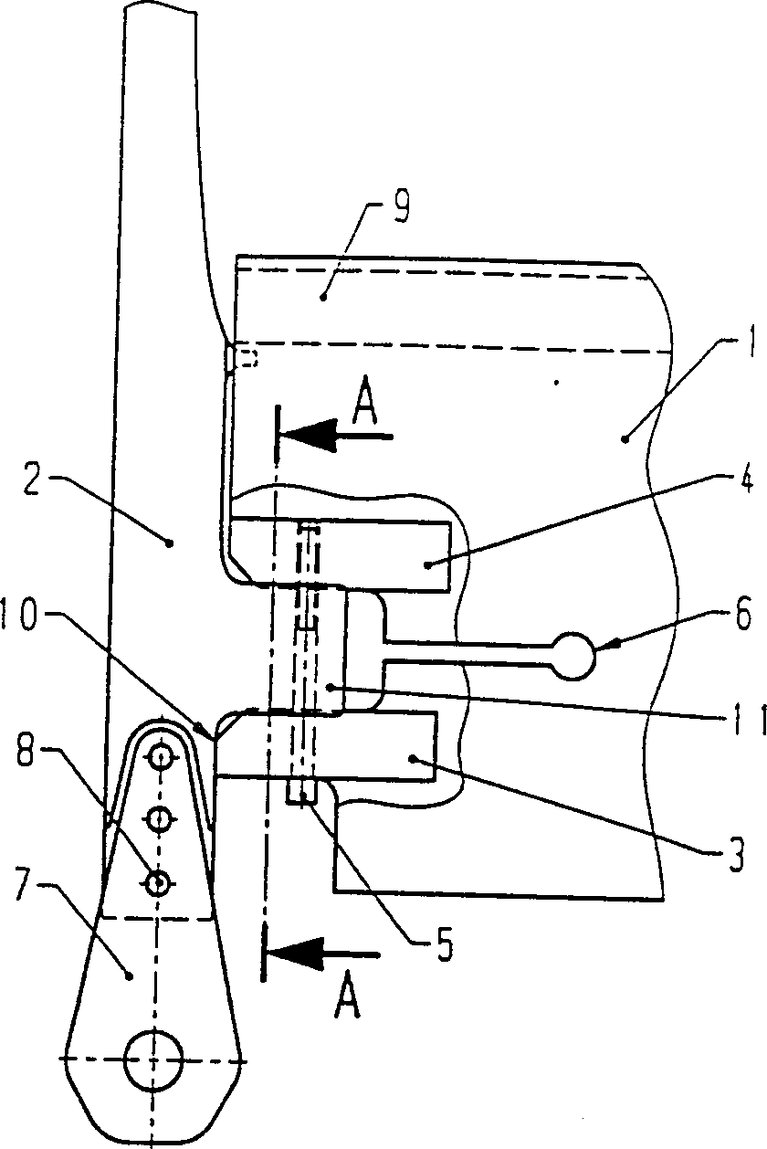
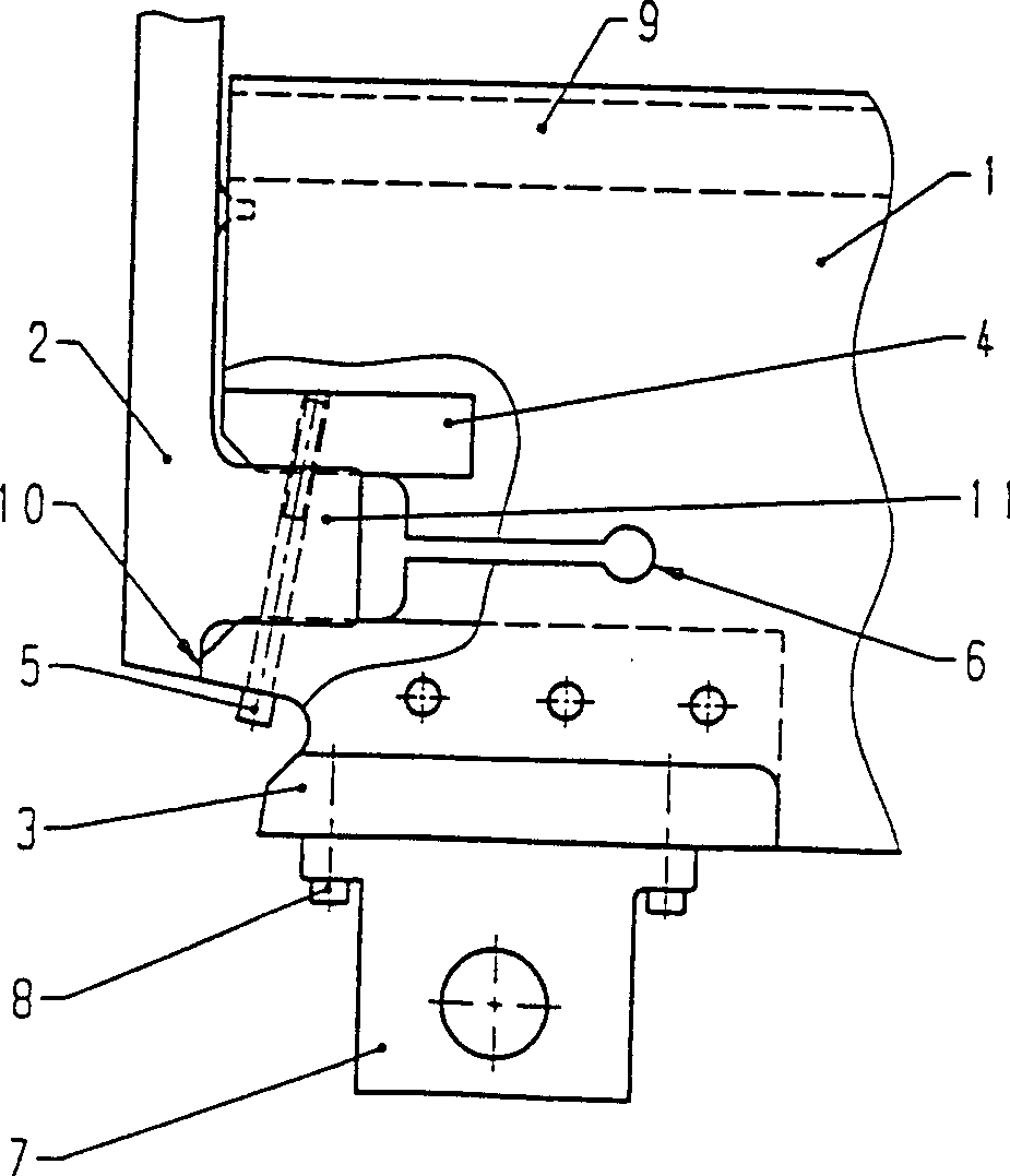
[0019] figure 1 It shows a longitudinal section of a structure of the new corner connection device proposed by the present invention. In an empty heddle plate 1 on which the heald guide bar 9 is fastened, a projection 11 of the side support arm 2 engages in two guide elements fixedly arranged on the heald plate 1 , namely the stop element 3 and the Between the threaded plates 4. The protrusion 11 of the side support arm is held by means of the locking screw 5 between the stop element 3 fixed on the heddle plate 1 and the threaded plate 4 also fixed on the heddle plate 1, at this time the stop element 3 is held Press against threaded plate 4. This is possible because the heald panels acquire a certain elasticity by means of the slots 6 in the end regions of the heald panels. Furthermore, the locking element 3 has a machined surface 10 for positioning the side support arm 2 in the longitudinal direction of the heddle profile 1 . Finally, press figure 1 In the structure show...


PUM


Abstract

The invention discloses a heald frame corner connecting device. In order to connect the heald plate (1) of the heald frame with the side support arm (2) of the heald frame, at least one guide surface is set on the heald plate (1). The guide surface extends at least approximately parallel to the longitudinal axis of the heald plate. In addition, the guide surface positively engages with at least one further guide surface on the projection (11) of the side support arm (2), which extends at least approximately parallel to the sheath plate or perpendicularly to the side support arm.

Description

technical field [0001] Modern weaving machines place ever higher demands on the precision of the attachments. This is especially true for heald frames. Heald frames are subjected to high accelerations during weaving operations. In order to avoid additional loads, it is imperative, for example, to guide the heald frames with sufficient precision. However, an essential prerequisite for this is that the heald frame is manufactured with sufficient precision. In addition, they must be designed in such a way that for the drawing-in of the heddles, the side support arms can be easily disassembled and then reassembled with the original precision. The result of frequent product changes in weaving mills is that heddle boards and side support arms are mixed up. More precisely manufactured components can only solve this problem to a small extent because of the inevitable large variances in batch-to-batch manufacturing. Therefore, a new design solution is required. None of the hither...

Claims


Application Information

Patent Timeline
IPC IPC(8): B65H18/06D03C9/06D03D49/20
CPCD03C9/0675D03C9/0683
Inventor 汉斯·鲍曼
Owner GROZ BECKERT KG
Why Eureka
Try Eureka