Solid state electrochromic element and mirror device and CRT display comprising it

An electrochromic device and electrochromic layer technology, which can be applied to parts of TV systems, electrical components, parts of color TVs, etc., and can solve problems such as size increase

Inactive Publication Date: 2002-11-20
MURAKAMI CORP
View PDF0 Cites 8 Cited by
  • Summary
  • Abstract
  • Description
  • Claims
  • Application Information

AI Technical Summary

Problems solved by technology

However, this approach disadvantageously results in an increase in the size of the solid-state EC device 30B as a filter for a CRT display

Method used


Image

  • Solid state electrochromic element and mirror device and CRT display comprising it
  • Solid state electrochromic element and mirror device and CRT display comprising it
  • Solid state electrochromic element and mirror device and CRT display comprising it

Examples


Embodiment Construction

[0025] Preferred embodiments of the present invention will be described below with reference to the accompanying drawings.

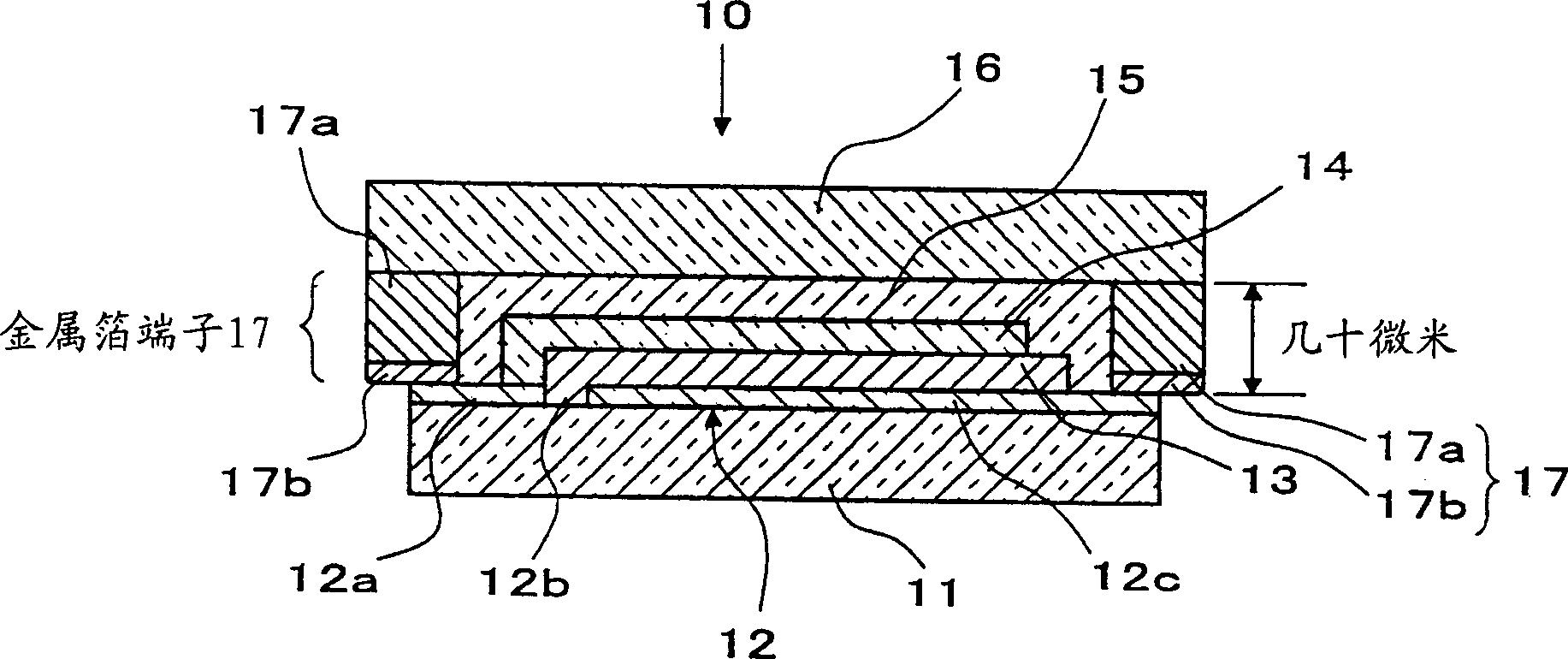
[0026] first reference figure 1 , will introduce a solid-state EC device according to an embodiment of the present invention. figure 1 is a cross-sectional view of a solid-state EC device according to an embodiment of the present invention.

[0027] Such as figure 1 As shown, a solid EC device 10 has a lower transparent conductive coating 12 formed of ITO or the like on the upper surface of a glass substrate 11, and a groove 12b is formed in a portion of the lower transparent conductive coating 12 to provide an insulating portion 12a. The lower transparent conductive coating 12 consists of two parts, namely an insulating part 12a and a main part 12c insulated with grooves 12b, so that terminals for the two electrodes are obtained from these parts. The width dimension of the lower transparent conductive coating 12 including the insulating portion 12a ...


PUM


Abstract

Provided is a solid-state electrochromic device, comprising a lower transparent conductive coating (12) formed as a thin film on a glass substrate, and partially provided with grooves (12b) and insulated by the grooves (12b); stacked on the lower an electrochromic layer (13) on the transparent conductive coating (12); and an upper transparent conductive coating (14) in direct contact with the insulating portion (12a) of the lower transparent conductive coating. A metal foil terminal (17) made of a metal foil (17a) applied thereto with a conductive adhesive material bonded to the end of the main body portion (12c) of the lower transparent conductive coating and insulation of the lower transparent conductive coating end of part (12a).

Description

technical field [0001] The present invention relates to solid state electrochromic devices using metal foil terminals as lead-in terminals for device electrodes and mirror system and CRT (or cathode ray tube) displays using such devices. Background technique [0002] The reversible transition between colored and colorless states caused by oxidation or reduction reversibly produced by the application of a voltage is called electrochromism. Electrochromic (hereinafter referred to as EC) devices using materials having such electrochromic characteristics and indicating a change in color state by controlling a voltage are used in display devices, light quantity control devices, and the like in various industrial fields. [0003] Examples of conventional solid-state EC devices are shown in Figure 6 middle. In the solid-state EC device 30, a lower transparent conductive coating 32 made of indium tin oxide (ITO) or the like is provided on a glass substrate 31, and a groove 32b is ...

Claims


Application Information

Patent Timeline
Patent Type & Authority Applications(China)
IPC IPC(8): G02F1/153G02F1/155G02F1/161H04N5/65H04N5/72
CPCG02F1/153G02F1/155G02F1/161H04N5/65H04N5/72
Inventor 持塚多久男寺田佳之
Owner MURAKAMI CORP
Why Eureka
Try Eureka