

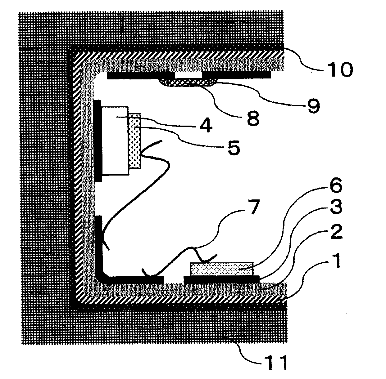
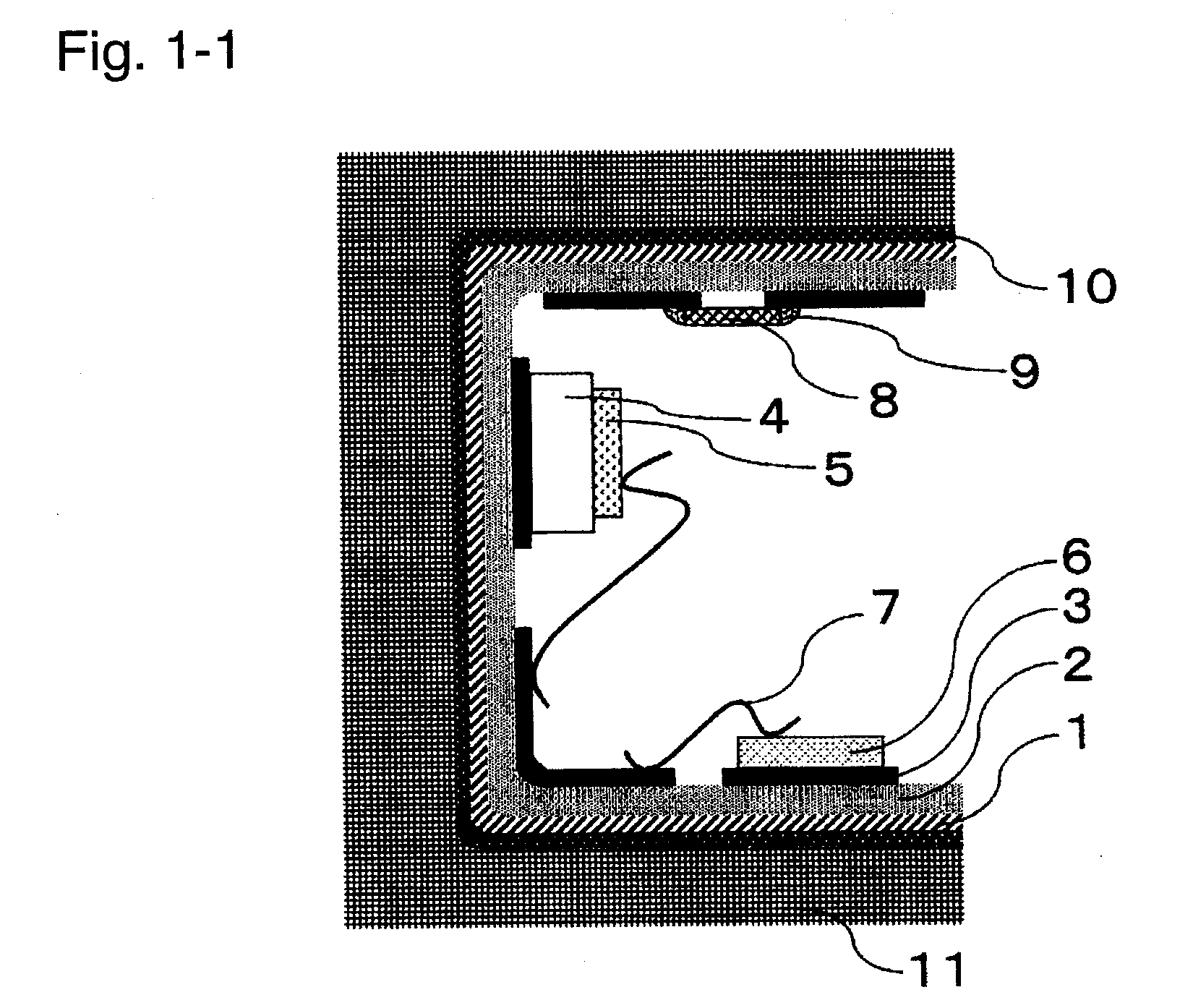
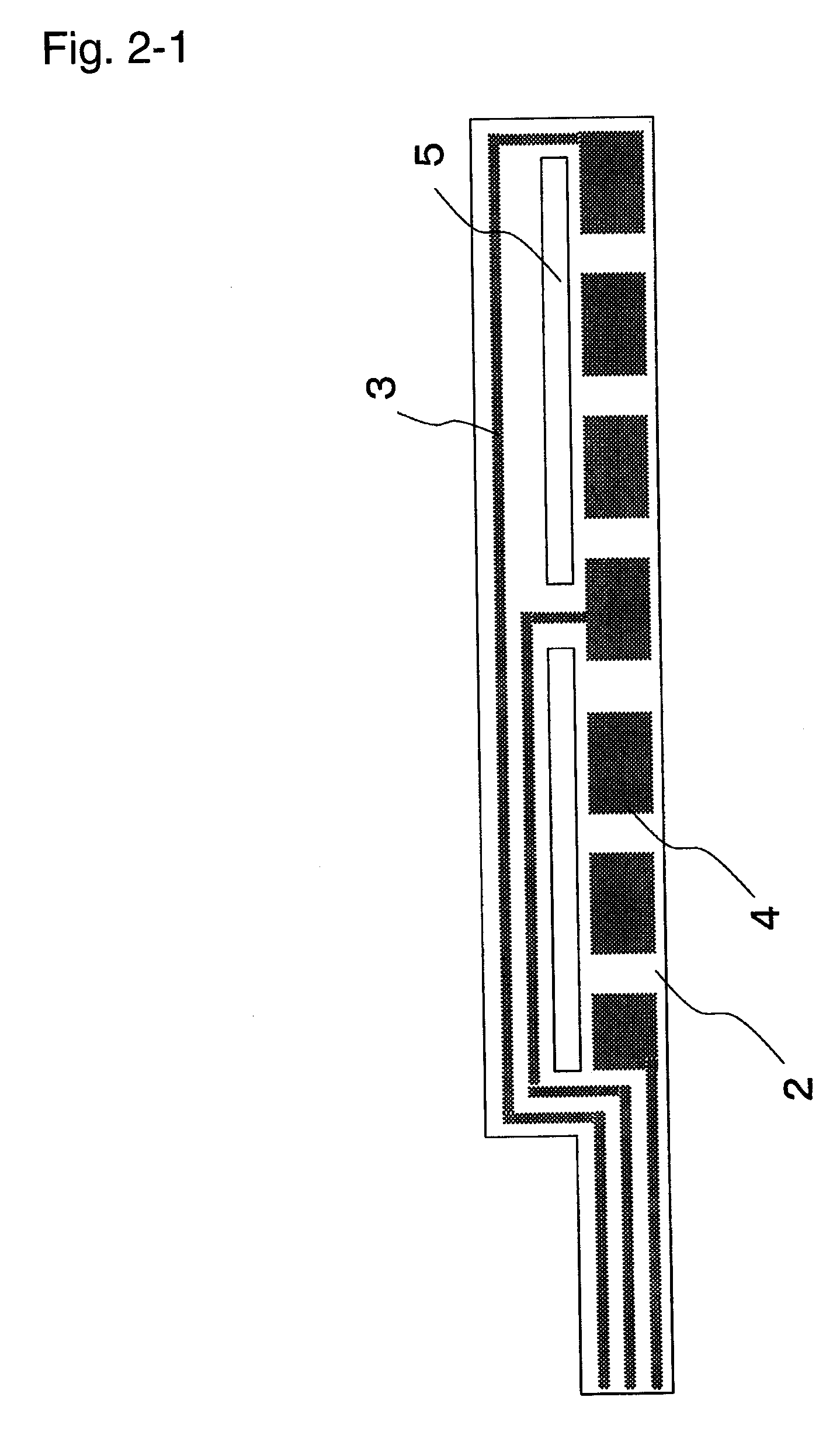
Metal base circuit board, LED, and LED light source unit
a technology of led light source and metal base, which is applied in the direction of laminating printed circuit boards, semiconductor devices for light sources, lighting and heating apparatus, etc. it can solve the problems of difficult to reduce the thickness, and limited installation sites, so as to reduce the size or thickness of electronic equipment, reduce heat accumulation, and easy to bend
- Summary
- Abstract
- Description
- Claims
- Application Information
AI Technical Summary
Benefits of technology
Problems solved by technology
Method used
Image

Examples
example 1-1
[0124]As shown in Table 1-1, to 100 parts by mass of a bisphenol A epoxy resin having an epoxy equivalent of 187 (EPICLON830-S, manufactured by Dainippon Ink and Chemicals Incorporated), 63 parts by mass of a polyoxypropylenediamine (mass ratio of D-40 to D-2000 was 6:4, manufactured by HARTZMAN) was added as a curing agent, and pulverized aluminum oxide having an average particle size of 2.2 μm and a maximum particle size of 20 μm (AL-173, manufactured by Showa Denko K.K.) was blended so that it would be 50 vol % in an insulating layer, and an insulating layer was formed on an aluminum foil having a thickness of 40 μm so that the thickness after the curing would be 100 μm. Then, an electrolytic copper foil having a thickness of 35 μm was bonded, followed by heating to thermally cure the insulating layer thereby to obtain a metal base board. Further, with the obtained metal base substrate, predetermined positions were masked with an etching resist, the copper foil was then subjected...
example 1-2
[0127]As shown in Table 1-1, to 100 parts by mass of a hydrogenated (in Table 1, identified by Hydrogenated) bisphenol A epoxy resin having an epoxy equivalent of 201 (YX-8000, manufactured by Japan Epoxy Resins Co., Ltd.), 63 parts by mass of a polyoxypropylenediamine (mass ratio of D-400 to D-2000 was 6:4, manufactured by HARTZMAN) was added as a curing agent, and pulverized aluminum oxide having an average particle size of 2.2 μm and a maximum particle size of 20 μm (AL-173, manufactured by Showa Denko K.K.) was blended so that it would be 50 vol % in an insulting layer, and an insulating layer was formed on an aluminum foil having a thickness of 40 μm so that the thickness after curing would be 100 μm. Then, an electrolytic copper foil having a thickness of 35 μm was bonded, followed by heating to thermally cure the insulating layer thereby to obtain a metal base board. Except for the above, in the same manner as in Example 1-1, a metal base circuit board was prepared, and vario...
example 1-3
[0129]As shown in Table 1-1, to 100 parts by mass of an epoxy resin comprising 70 mass % of a hydrogenated bisphenol A epoxy resin having an epoxy equivalent of 201 (YX-8000, manufactured by Japan Epoxy Resins Co., Ltd.) and 30 mass % of a bisphenol A epoxy resin having an epoxy equivalent of 1,900 (YD-927H, manufactured by Tohto Kasei Co., Ltd.), 48 parts by mass of a polyoxypropylenediamine (mass ratio of D-400 to D-2000 was 6:4, manufactured by HARTZMAN) was added as a curing agent, and pulverized aluminum oxide having an average particle size of 2.2 μm and a maximum particle size of 20 μm (AL-173, manufactured by Showa Denko K.K.) was blended so that it would be 50 vol % in an insulting layer, and an insulating layer was formed on an aluminum foil having a thickness of 40 μm, so that the thickness after curing would be 100 μm. Then, an electrolytic copper foil having a thickness of 35 μm was bonded, followed by heating to thermally cure the insulating layer thereby to obtain a m...
PUM
 Abstract
Description
Claims
Application Information