Substrate and collector grid structures for integrated series connected photovoltaic arrays and process of manufacture of such arrays

a technology of photovoltaic arrays and collector grids, which is applied in the direction of solid-state devices, power plants, transportation and packaging, etc., can solve the problems of high cost of single crystal silicon material and interconnection processing, thwarting wide-scale energy collection using single-crystal silicon cells, and reducing the efficiency of photovoltaic energy collection,

Inactive Publication Date: 2009-03-24
SOLANNEX
View PDF64 Cites 91 Cited by
  • Summary
  • Abstract
  • Description
  • Claims
  • Application Information

AI Technical Summary

Benefits of technology

[0045]An object of the invention is to eliminate the deficiencies in the prior art methods of producing expansive area, series interconnected photovoltaic arrays. A further object of the present invention is to provide improved substrates to achieve series interconnections among expansive thin film cells.
[0046]A further object of the invention is to permit inexpensive production of high efficiency, heat treated thin film photovoltaic cells while simultaneously permitting the use of polymer based substrate materials and associated processing to effectively interconnect those cells.
[0047]A further object of the present invention is to provide improved processes whereby expansive area, series interconnected photovoltaic arrays can be economically mass produced.
[0050]The current invention provides a solution to the stated need by producing the active photovoltaic film and interconnecting substrate separately and subsequently combining them to produce the desired expansive series interconnected array. The invention contemplates deposition of thin film photovoltaic junctions on metal foil substrates which can be heat treated following deposition in a continuous fashion without deterioration of the metal support structure. In a separate operation, an interconnection substrate structure is produced in a continuous roll-to-roll fashion.
[0051]The metal foil supported photovoltaic junction is then laminated to the interconnecting substrate structure and conductive connections are deposited to complete the array. In this way the interconnection substrate structure can be uniquely formulated from polymer-based materials since it does not have to endure high temperature exposure. Furthermore, the photovoltaic junction and its metal foil support can be produced in bulk without the need to use the expensive and intricate material removal operations currently taught in the art to achieve series interconnections.

Problems solved by technology

Despite good conversion efficiencies and long-term reliability, widespread energy collection using single-crystal silicon cells is thwarted by the exceptionally high cost of single crystal silicon material and interconnection processing.
Despite significant improvements in individual cell conversion efficiencies for both single crystal and thin film approaches, photovoltaic energy collection has been generally restricted to applications having low power requirements.
One factor impeding development of bulk power systems is the problem of economically collecting the energy from an extensive collection surface.
It is readily recognized that making effective, durable series connections among multiple small cells can be laborious, difficult and expensive.
However, a challenge still remains regarding subdividing the expansive films into individual cells followed by interconnecting into a series connected array.
The electrical resistance of thin vacuum metallized layers significantly limits the active area of the individual interconnected cells.
Use of a glass or ceramic substrates generally restricts one to batch processing and handling difficulty.
However, despite the fact that use of a metal foil allows high temperature processing in roll-to-roll fashion, the subsequent interconnection of individual cells effectively in an interconnected array has proven difficult, in part because the metal foil substrate is electrically conducting.
These operations add considerably to the final interconnected array cost.
These material removal techniques are troublesome for a number of reasons.
First, many of the chemical elements involved in the best photovoltaic semiconductors are expensive and environmentally unfriendly.
This removal subsequent to controlled deposition involves containment, dust and dirt collection and disposal, and possible cell contamination.
This is not only wasteful but considerably adds to expense.
Secondly, the removal processes are difficult to control dimensionally.
Thus a significant amount of the valuable photovoltaic semiconductor is lost to the removal process.
Ultimate module efficiencies are further compromised in that the spacing between adjacent cells grows, thereby reducing the effective active collector area for a given module area.
A further unsolved problem which has thwarted production of 
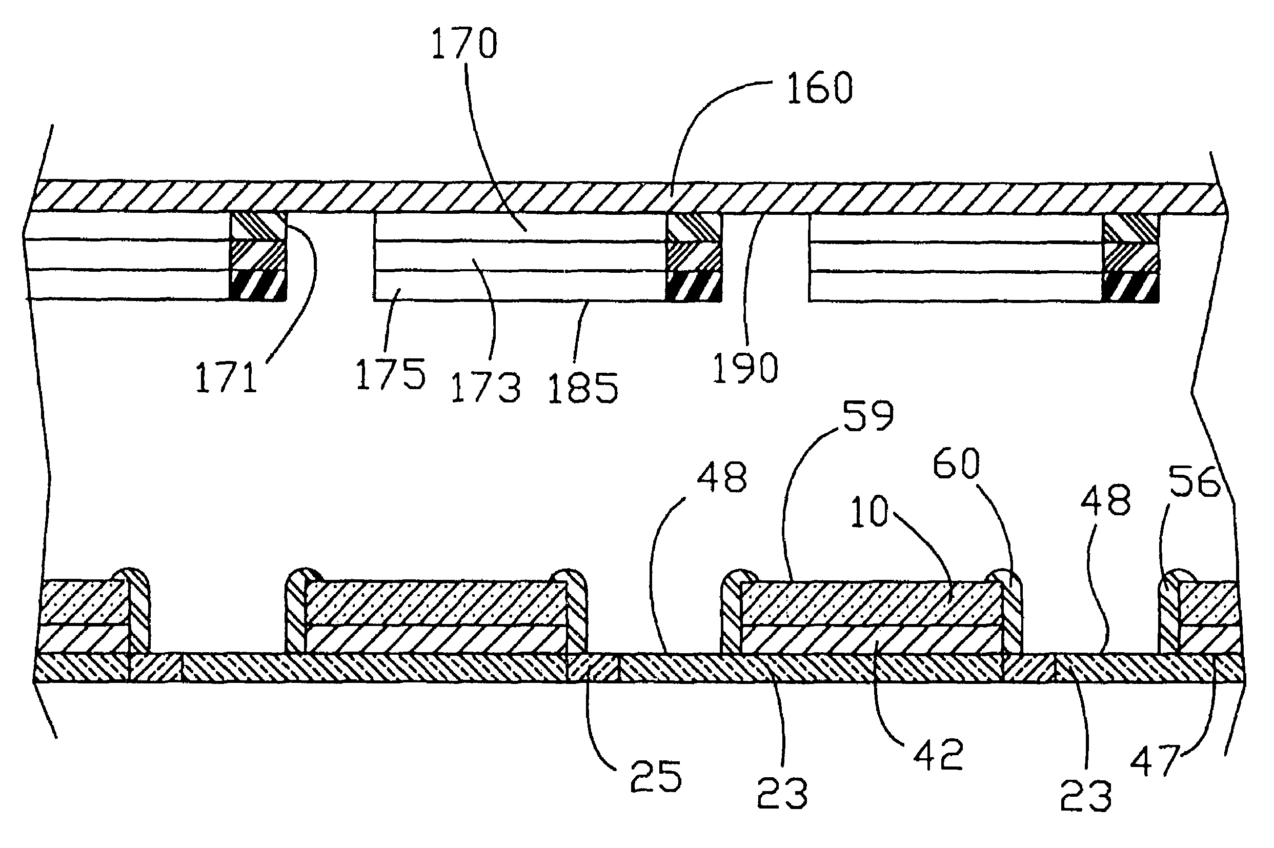
expansive surface photovoltaic modules is that of collecting the photogenerated current from the top, light incident surface.
However, these TCO layers are relatively resistive compared to pure metals.
These small cell widths demand very fine interconnect area widths, which dictate delicate and sensitive techniques to be used to electrically connect the top TCO surface of one cell to the bottom electrode of an adjacent series connected cell.
Furthermore, achieving good stable ohmic contact to the TCO cell surface has proven difficult, especially when one employs those sensitive techniques available when using the TCO only as the top collector electrode.
The problem of collecting photovoltaic generated current from the top light impinging surface of a photovoltaic cell has been addressed in a number of ways, none entirely successful.
The process is very sensitive to processing variables used to fabricate the plastic substrate, limiting applications to carefully molded parts and designs.
In addition, the many steps employing harsh chemicals make the process intrinsically costly and environmentally difficult.
Finally, the sensitivity of ABS plastic to liquid hydrocarbons has prevented certain applications.
None of these attempts at simplification have achieved any recognizable commercial application.
Efforts to advance systems contemplating metal electrodeposition directly onto the surface of an electrically conductive polymer have encountered a number of obstacles.
The first is the combination of fabrication difficulty and material property deterioration brought about by the heavy filler loadings often required.
A second is the high cost of many conductive fillers employed such as silver flake.
Another major obstacle involved in the electroplating of electrically conductive polymers is a consideration of adhesion between the electrodeposited metal and polymeric substrate (metal / polymer adhesion).
In some cases such as electroforming, where the electrodeposited metal is eventually removed from the substrate, metal / polymer adhesion may actually be detrimental.
However, in most cases sufficient adhesion is required to prevent metal / polymer separation during extended environmental and use cycles.
However, here the metal particles are generally encapsulated by the resin binder, often resulting in a resin rich “skin”.
An additional major obstacle confronting development of electrically conductive polymeric resin compositions capable of being directly electroplated is the initial “bridge” of electrodeposit on the surface of the electrically conductive resin.
However, if the contact resistance is excessive or the substrate is insufficiently conductive, the electrodeposit current favors the rack tip to the point where the electrodeposit will not bridge to the substrate.
Moreover, a further problem is encountered even if specialized racking successfully achieves electrodeposit bridging to the substrate.
The polymeric substrate can be relatively limited in the amount of electrodeposition current which it alone can convey.
In a fashion similar to the bridging problem discussed above, the electrodeposition current favors the electrodeposited metal and the lateral growth can be extremely slow and erratic.
This restricts the size and “growth length” of the substrate conductive pattern, increases plating costs, and can also result in large non-uniformities in electrodeposit integrity and thickness over the pattern.
These factors of course work against achieving the desired result.
However, attempts to make an acceptable directly electroplateable resin using the relatively small metal containing fillers alone encounter a number of barriers.
First, the fine metal containing fillers are relatively expensive.
The loadings required to achieve the particle-to-particle proximity to achieve acceptable conductivity increases the cost of the polymer / filler blend dramatically.
The metal containing fillers are accompanied by further problems.
They tend to cause deterioration of the mechanical properties and processing characteristics of many resins.
This significantly limits options in resin selection.
A required heavy loading of metal filler severely restricts ability to manipulate processing properties in this way.
A further problem is that metal fillers can be abrasive to processing machinery and may require specialized screws, barrels, and the like.
Finally, despite being electrically conductive, a simple metal-filled polymer still offers no mechanism to produce adhesion of an electrodeposit since the metal particles are generally encapsulated by the resin binder, often resulting in a non-conductive resin-rich “skin”.
For the above reasons, fine metal particle containing plastics have not been widely used as substrates for directly electroplateable articles.
A fundamental problem remaining unresolved by the Adelman teaching is the relatively high resistivity of carbon loaded polymers.
Thus, the electrodeposit bridging and coverage rate problems described above remained unresolved by the Adelman teachings.
Conventional “electroless” plating technology does not permit this compositional flexibility.
Conventional “electroless” plating technology does not permit great flexibility to “custom formulate”.
Due to multiple performance problems associated with their intended end use, none of the attempts identified above to directly electroplate electrically conductive polymers or plastics has ever achieved any recognizable commercial success.
One readily recognizes that the demand for such functional applications for electroplated articles is relatively recent and has been particularly explosive during the past decade.

Method used


Image

  • Substrate and collector grid structures for integrated series connected photovoltaic arrays and process of manufacture of such arrays
  • Substrate and collector grid structures for integrated series connected photovoltaic arrays and process of manufacture of such arrays
  • Substrate and collector grid structures for integrated series connected photovoltaic arrays and process of manufacture of such arrays

Examples


Embodiment Construction

[0139]Reference will now be made in detail to the preferred embodiments of the invention, examples of which are illustrated in the accompanying drawings. In the drawings, like reference numerals designate identical or corresponding parts throughout several views and an additional letter designation is characteristic of a particular embodiment.

[0140]Referring to FIGS. 1 and 2, a thin film photovoltaic cell is generally indicated by numeral 10. Cell 10 has a light-incident top surface 59 and a bottom surface 66. Structure 10 has a width X-10 and length Y-10. Width X-10 defines a first photovoltaic cell terminal edge 45 and second photovoltaic cell terminal edge 46. It is contemplated that length Y-10 is considerably greater than width X-10 and length Y-10 can generally be described as “continuous” or being able to be processed in a roll-to-roll fashion. FIG. 2 shows that cell 10 comprises a thin film semiconductor structure 11 supported by metal-based foil 12. Foil 12 has first surfac...


PUM

PropertyMeasurementUnit
voltageaaaaaaaaaa
widthsaaaaaaaaaa
thicknessaaaaaaaaaa

Abstract

This invention comprises deposition of thin film photovoltaic junctions on metal substrates which can be heat treated following deposition in a continuous fashion without deterioration of the metal support structure. In a separate operation an interconnection substrate structure is produced in a continuous roll-to-roll fashion. In this way the interconnection substrate structure can be uniquely formulated from polymer-based materials since it does not have to endure high temperature exposure. Cells comprising the metal foil supported photovoltaic junctions are then laminated to the interconnection substrate structure. Conductive interconnections are deposited to complete the array. The conductive interconnections can be accomplished with a separately prepared interconnection component. The interconnected array is produced using continuous roll-to-roll processing which avoids the need to use the expensive and intricate material removal operations currently taught in the art to achieve electrical interconnections among arrays of photovoltaic cells.

Description

CROSS-REFERENCE TO RELATED APPLICATIONS[0001]This application is a Continuation-in-Part of U.S. patent application Ser. No. 10 / 186,546 filed Jul. 1, 2002 now abandoned, entitled Substrate and Collector Grid Structures for Integrated Series Connected Photovoltaic Arrays and Process of Manufacture of Such Arrays, which is a Continuation-in-Part of U.S. patent application Ser. No. 09 / 528,086, filed Mar. 17, 2000, entitled Substrate and Collector Grid Structures for Integrated Series Connected Photovoltaic Arrays and Process of Manufacture of Such Arrays, and now U.S. Pat. No. 6,414,235, which is a Continuation-in-Part of U.S. patent application Ser. No. 09 / 281,656, filed Mar. 30, 1999, entitled Substrate and Collector Grid Structures for Electrically Interconnecting Photovoltaic Arrays and Process of Manufacture of Such Arrays, and now U.S. Pat. No. 6,239,352. The entire contents of the above identified applications are incorporated herein by this reference.BACKGROUND OF THE INVENTION[...

Claims


Application Information

Patent Timeline
Patent Type & Authority Patents(United States)
IPC IPC(8): H01L31/00H01L31/05
CPCH01L31/0465H01L31/0392H01L31/0508H01L31/0504Y02E10/52Y10T156/10Y10T428/12049Y10T156/1097H01L31/0445Y02E10/50
Inventor LUCH, DANIEL
Owner SOLANNEX
Why Eureka
Try Eureka