
Robot cleaning machine, robot cleaning system and method for controlling them

A cleaning system and robot technology, applied in the field of robot cleaning machines, can solve problems such as reducing cleaning efficiency

Inactive Publication Date: 2002-11-27
SAMSUNG GWANGJU ELECTRONICS CO LTD
View PDF0 Cites 105 Cited by
  • Summary
  • Abstract
  • Description
  • Claims
  • Application Information

AI Technical Summary

Problems solved by technology

In this way, the cleaning efficiency is reduced

Method used


Image

  • Robot cleaning machine, robot cleaning system and method for controlling them
  • Robot cleaning machine, robot cleaning system and method for controlling them
  • Robot cleaning machine, robot cleaning system and method for controlling them

Examples


Embodiment Construction

[0028] Hereinafter, preferred embodiments of the present invention will be described in detail with reference to the accompanying drawings.

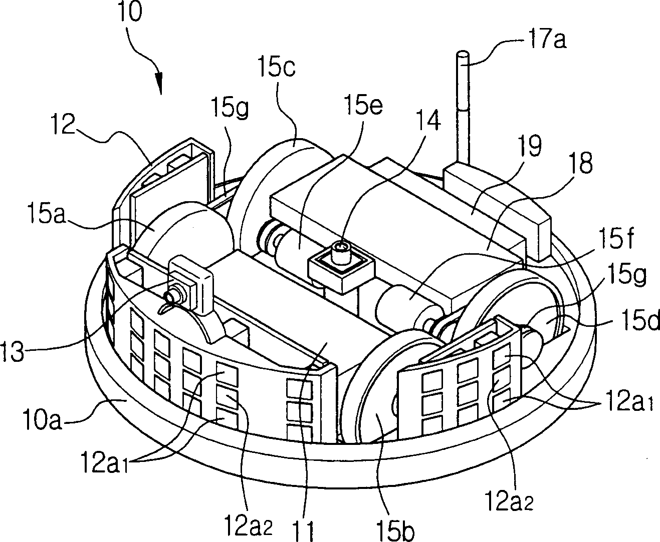
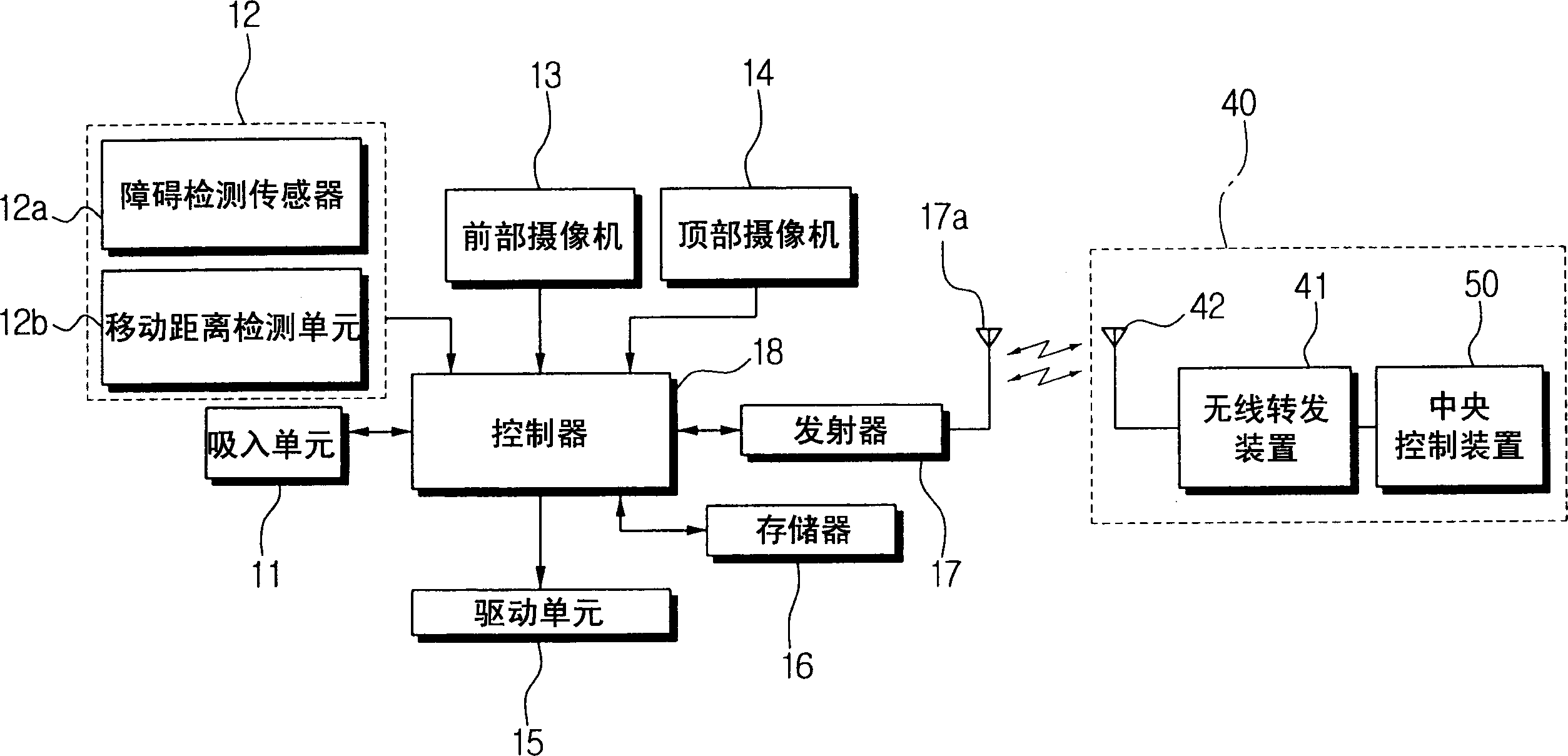
[0029] see figure 1 and figure 2 , the robot cleaning machine 10 includes a suction unit 11 , a sensing unit 12 , a front camera 13 , a top camera 14 , a drive unit 15 , a memory 16 , a transmitter 17 and a controller 18 . Reference numeral 19 is a battery.

[0030] The suction unit 11 is installed on the main body 10a so as to collect dust on the ground when air is sucked. The suction unit 11 is constructed by a well-known method. As an example, the suction unit 11 has a suction motor (not shown), and a suction chamber that collects sucked air from a suction hole or a suction pipe formed opposite to the floor by driving the suction motor.

[0031] The sensing unit 12 sends a signal to the outside. The sensing unit 12 includes an obstacle detection sensor 12a mounted at a predetermined interval on the peripheral side of the main bo...


PUM


Abstract

A robotic cleaning machine, a robotic cleaning system, and methods of controlling them. A robot cleaning machine that performs cleaning work by wirelessly communicating with an external device includes: a driving unit for driving a plurality of wheels; a top camera mounted on the main body for taking an upper image perpendicular to the direction of travel; and controlling the driving unit In order to drive the robot cleaning machine to drive in the cleaning area according to the predetermined driving route, and to correct the driving route by analyzing the image captured by the top camera. According to the robot cleaning machine, the robot cleaning system, and the method of controlling them, the position can be more accurately recognized using the upper image having relatively little change compared with the floor. Therefore, the movement error to reach the target position is reduced, and the commanded work can be performed more easily.

Description

technical field [0001] The present invention relates to a robot cleaning machine, a robot cleaning system and a method of controlling them, in particular to a robot cleaning machine capable of controlling the running of the robot cleaning machine by using an upper image taken while the robot cleaning machine is running, a robot cleaning system and a method of controlling them . Background technique [0002] A commonly used robot cleaning machine determines the cleaning area by driving through the peripheral trajectory of the cleaning area surrounded by walls or obstacles using an ultrasonic sensor installed in the main body, and designs a cleaning route to clean the determined cleaning area. Thereafter, the robot cleaner drives the wheels to move along the designed cleaning route by calculating the travel distance and current position from the signals detected by the sensors for sensing the number of rotations and the rotation angle of the wheels. However, the above-mention...

Claims


Application Information

Patent Timeline
IPC IPC(8): A47L9/00A47L9/28G05D1/02
CPCG05D1/0246G05D1/0272G05D1/0274G05D1/0282A47L9/009A47L9/2805A47L9/2852A47L9/2857A47L9/2884A47L9/2894A47L2201/04
Inventor 宋贞坤高将然文承彬李炅武
Owner SAMSUNG GWANGJU ELECTRONICS CO LTD
Features
  • Generate Ideas
  • Intellectual Property
  • Life Sciences
  • Materials
  • Tech Scout
  • Unparalleled Data Quality
  • Higher Quality Content
  • 60% Fewer Hallucinations
Learn More