Method for controlling reactive power and device for generating electrical energy in electrical network

A technology of adjusting device and electric power, applied in reactive power adjustment/elimination/compensation, circuit device, active power filtering and other directions, which can solve problems such as occupation, side effects of phase-shift capacitors on grid stability, large space, etc.

Inactive Publication Date: 2002-11-27
阿洛伊斯沃本
View PDF0 Cites 1 Cited by
  • Summary
  • Abstract
  • Description
  • Claims
  • Application Information

AI Technical Summary

Problems solved by technology

However, full compensation of inductive reactive power by phase-shifting capacitors is not practically possible when high power fluctuations are involved
A further disadvantage is that the required phase-shifting capacitors have a negative effect on the stability of the grid. These capacitors are often combined to form so-called capacitive batteries and they take up a lot of space.

Method used


Image

  • Method for controlling reactive power and device for generating electrical energy in electrical network
  • Method for controlling reactive power and device for generating electrical energy in electrical network
  • Method for controlling reactive power and device for generating electrical energy in electrical network

Examples


Embodiment Construction

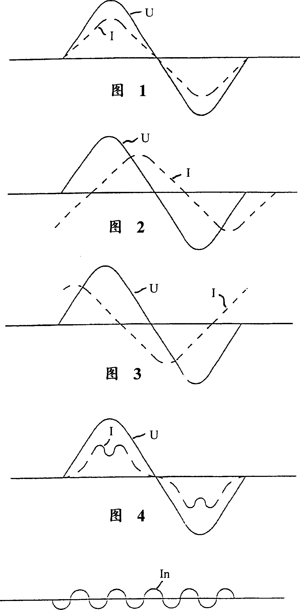
[0018] It has long been known that fundamental harmonic oscillating reactive power can occur in grids. Figures 1 to 3 show various voltage and current configurations.

[0019] Figure 1 shows a situation where there is no reactive power, that is to say the voltage U and the current I have no phase shift. The current neither leads nor lags the voltage. Therefore there is no fundamental harmonic oscillating reactive power.

[0020] FIG. 2 shows a situation in which the current I lags the voltage U in time. In this case, inductive reactive power is required, which is the case for most consumers since they, such as electric motors, have inductors.

[0021] FIG. 3 shows a situation in which the current I precedes the voltage U in time. In this case, capacitive reactive power is required.

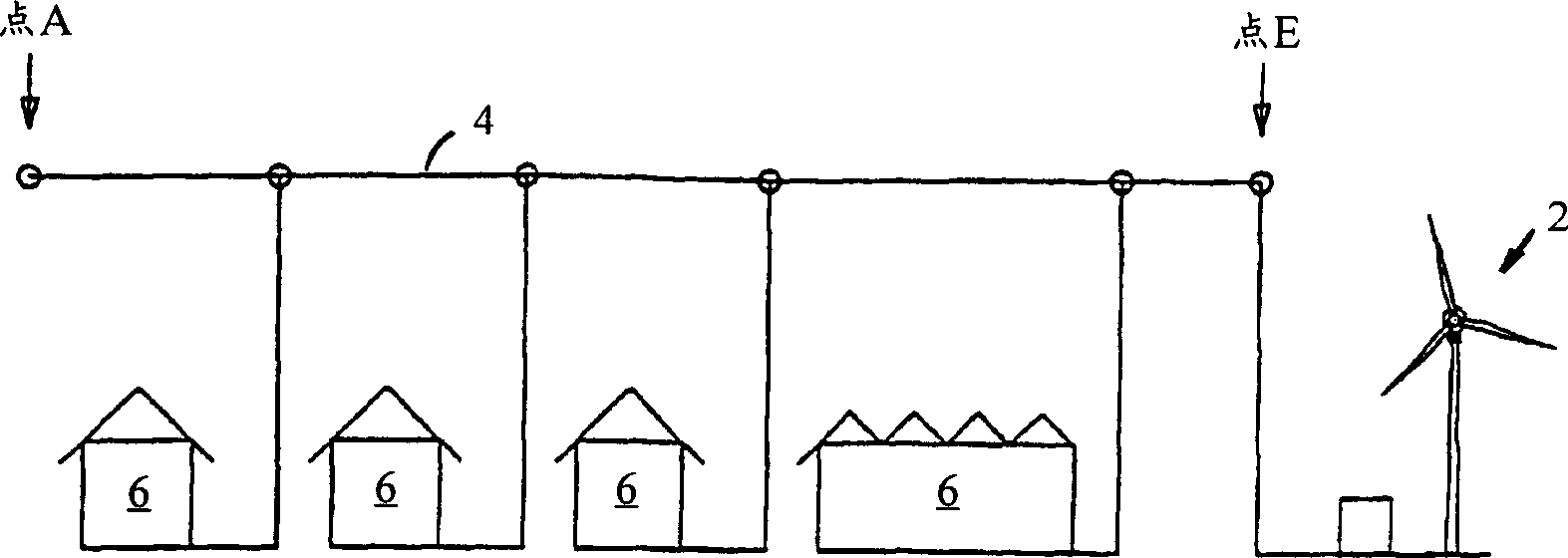
[0022] Image 6 An arrangement is shown in which a wind power installation 2 is connected to a network branch. The individual consumers 6 are connected from the beginning (point A) to the e...


PUM


Abstract

A method of reactive power regulation in an electrical network in which electrical power is produced by an electrical generator preferably driven by the rotor of a wind power installation and suitably modulated by means of a compensation device between the generator and the network for the compensation of reactive power, and an apparatus for producing electrical energy in an electrical network, preferably an electrical generator driven by the rotor of a wind power installation and a compensation device between the generator and the network for the compensation of reactive power. The compensation device is so regulated that the electrical power delivered to the consumer has a reactive power component which is adapted in respect of its phase, amplitude and / or frequency to the consumer in such a way as to compensate for the reactive power in the consumer.

Description

technical field [0001] The invention relates to a method for regulating reactive power in an electrical network, in which the electric power is produced by a generator, preferably driven by a rotor of a wind power installation and by means of a connection between the generator and the network for compensating the reactive power The compensation device is properly adjusted. The invention also relates to a device for generating electrical energy in a grid, comprising a generator, preferably driven by a rotor of a wind power installation, and a compensation device for reactive power compensation between the generator and the grid. Background technique [0002] Many grid-connected consumers require inductive reactive power. Compensation of such inductive reactive power components is achieved by using capacitors, also known as phase-shifting capacitors, whose capacitive and inductive reactances are approximately equal. However, full compensation of indu...

Claims


Application Information

Patent Timeline
Patent Type & Authority Applications(China)
IPC IPC(8): H02J3/50H02J3/01H02J3/16H02J3/18
CPCH02J3/01H02J3/1842Y02E40/40Y02E10/76Y02E40/20
Inventor 阿洛伊斯·沃本
Owner 阿洛伊斯沃本
Why Eureka
Try Eureka