Wireless communication device, and wireless communication method

A wireless communication device and wireless signal technology, applied in radio transmission systems, communication between multiple stations, antennas, etc., can solve the problems of not the most suitable way of sending data, poor transmission efficiency, etc.

Inactive Publication Date: 2002-12-04
PANASONIC CORP
View PDF1 Cites 63 Cited by
  • Summary
  • Abstract
  • Description
  • Claims
  • Application Information

AI Technical Summary

Problems solved by technology

[0004] However, since the line conditions change constantly, the method of transmitting data is often not the most suitable. For the line conditions, the array directivity or beam width of the best transmitting antenna is

Method used


Image

  • Wireless communication device, and wireless communication method
  • Wireless communication device, and wireless communication method
  • Wireless communication device, and wireless communication method

Examples


Embodiment 1

[0011] In this embodiment, the operation in the case where the quality information of the received signal is used for the channel condition will be described.

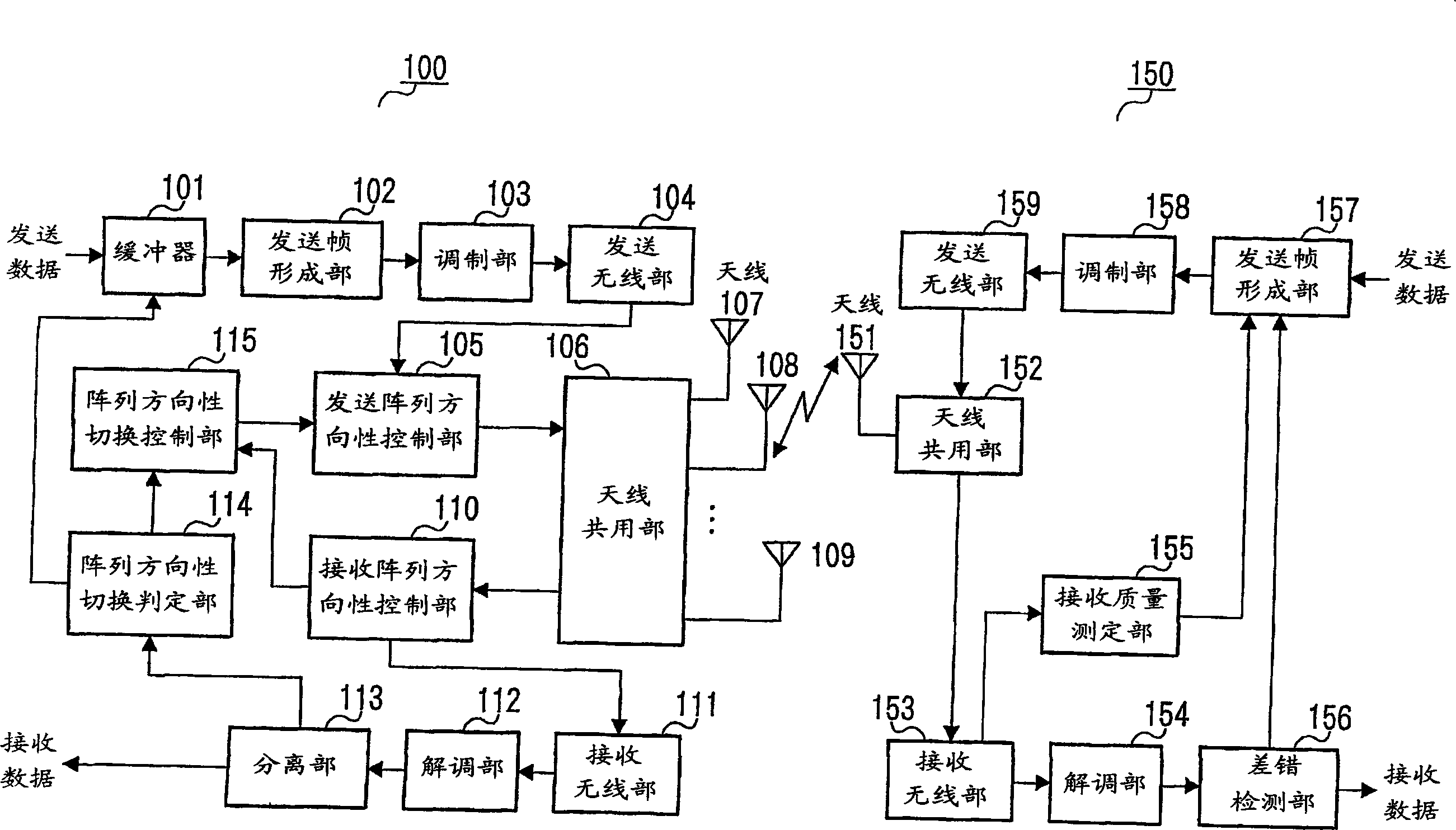
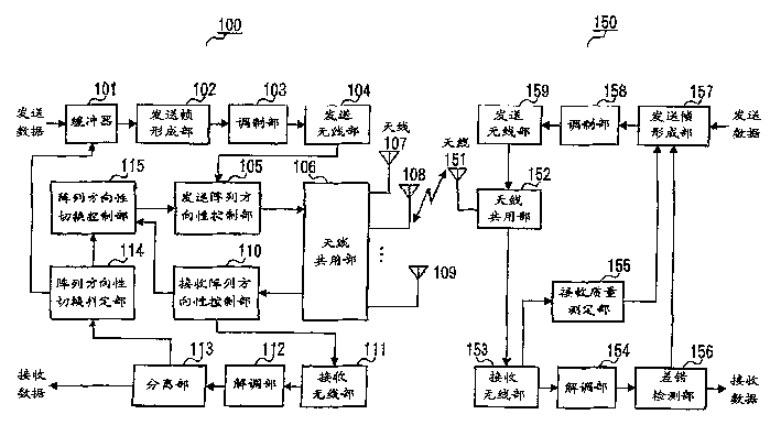
[0012] figure 1 A block diagram showing the configuration of the wireless communication apparatus according to Embodiment 1 of the present invention. exist figure 1 In this example, the wireless communication device 100 and the wireless communication device 150 perform wireless communication with each other.

[0013] The buffer 101 stores transmission data, and outputs the transmission data to the transmission frame formation unit 102 according to an instruction output from the array directivity switching determination unit 114 described later.

[0014] The transmission frame formation unit 102 forms a transmission frame from the transmission data output from the buffer 101 and outputs it to the modulation unit 103 .

[0015] The modulation unit 103 modulates the transmission frame and outputs it to the transmission...

Embodiment 2

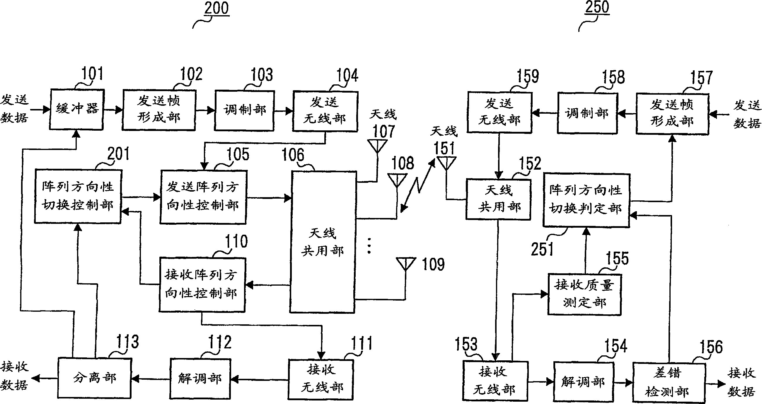
[0067] figure 2 A block diagram showing the configuration of a wireless communication device according to Embodiment 2 of the present invention. Among them, for figure 1 the same structure, with the figure 1 The same reference numerals are used, and detailed descriptions are omitted.

[0068] exist figure 2 In this example, the wireless communication device 200 and the wireless communication device 250 perform wireless communication with each other.

[0069] Buffer 101 stores transmission data, and outputs the transmission data to transmission frame formation unit 102 based on the ACK signal or NACK signal output from separation unit 113 .

[0070] Transmission array directivity control unit 105 weights the transmission signal output from transmission radio unit 104 according to an instruction from array directivity switching control unit 201 , and outputs it to antenna 107 , antenna 108 , and antenna 109 via antenna sharing unit 106 . The transmission array directivity...


PUM


Abstract

The array directivity switching determination unit 114 stores the reception quality information output from the separation unit 113, and determines whether to change the array directivity or beam width of the transmitting antenna based on the reception quality information, and determines whether to perform or not to change the transmitting antenna according to the determination result. The instruction of array directivity or beam width is output to the array directivity switching control unit 115 . When an instruction to switch the array directivity or beam width of the transmitting antenna is output from the array directivity switching determination unit 115, the array directivity switching control unit 115 calculates The weights transmitted by each antenna are output to the transmission array directivity control unit 105, and an instruction to change the array directivity or beam width of the transmission antennas is output.

Description

technical field [0001] The present invention relates to a wireless communication device and a wireless communication method, in particular to the array antenna control of the wireless communication device. Background technique [0002] In wireless communication, transmitted data cannot be received with correct values ​​due to the influence of paths and the like. In this case, the sending end sends the data to the receiving end, and the receiving end judges the error of the received data, and sends a retransmission request to the sending end if there is an error. Then, the transmitting end receives the retransmission request from the receiving end, and then transmits data with the same array directivity or beam width of the transmitting antenna as when the data was first transmitted. [0003] After the data is correctly received, when the transmitting end transmits the next data, it also transmits with the same array directivity or beam width of the...

Claims


Application Information

Patent Timeline
IPC IPC(8): H01Q3/26H04B7/06H04B7/10H04B7/26
CPCH04B7/0617H04B7/02
Inventor 相泽纯一青山高久星野正幸
Owner PANASONIC CORP
Why Eureka
Try Eureka