
Rectifying device, mounting device, rectifying method

A technology for installing heads and leads, applied to electrical components, electrical components, etc., can solve the problems of reduced production cycle, correction failure, and increase in the number of retries of correction actions, and achieve the effect of reducing risks

Active Publication Date: 2018-12-25
JUKI CORP
View PDF8 Cites 0 Cited by
  • Summary
  • Abstract
  • Description
  • Claims
  • Application Information

AI Technical Summary

Problems solved by technology

[0004] However, in the straightening device described in Patent Document 1, the amount of pressing of the lead member corresponding to the straightening tool is constant, so even if the straightening operation is repeated, the lead part cannot always be properly straightened.
In particular, the appropriate press-fitting amount of the lead parts changes according to the production lot, so that the following problems arise, that is, the number of retries of the corrective action increases and the production tact decreases, or the correction fails.

Method used


Image

  • Rectifying device, mounting device, rectifying method
  • Rectifying device, mounting device, rectifying method
  • Rectifying device, mounting device, rectifying method

Examples


Embodiment Construction

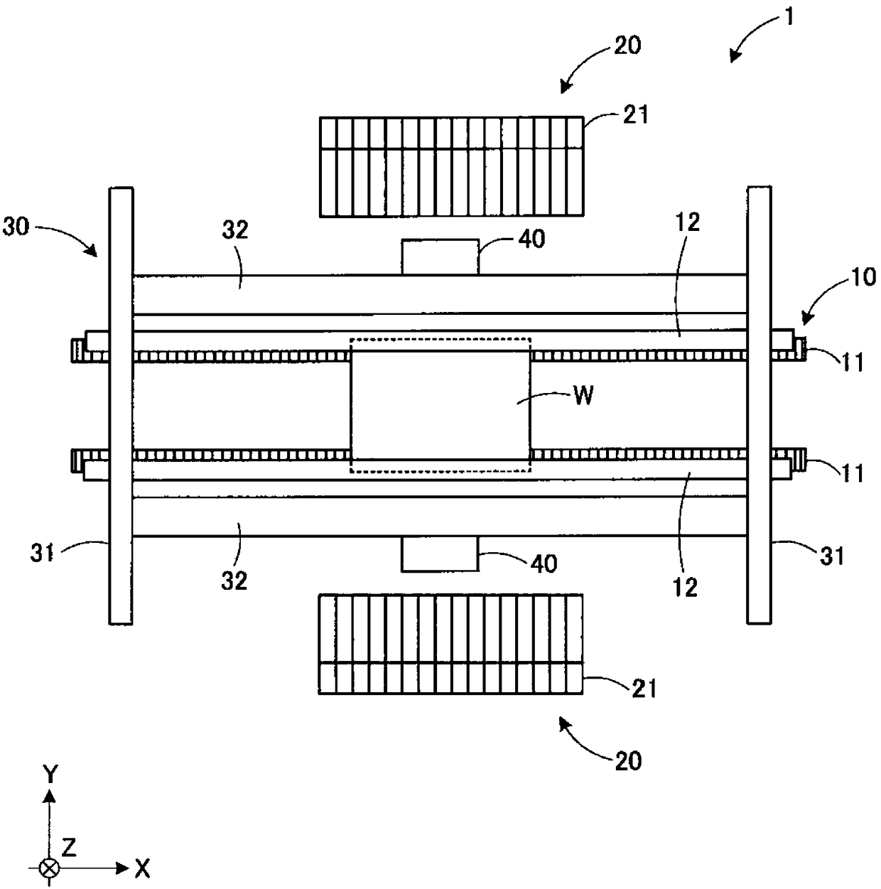
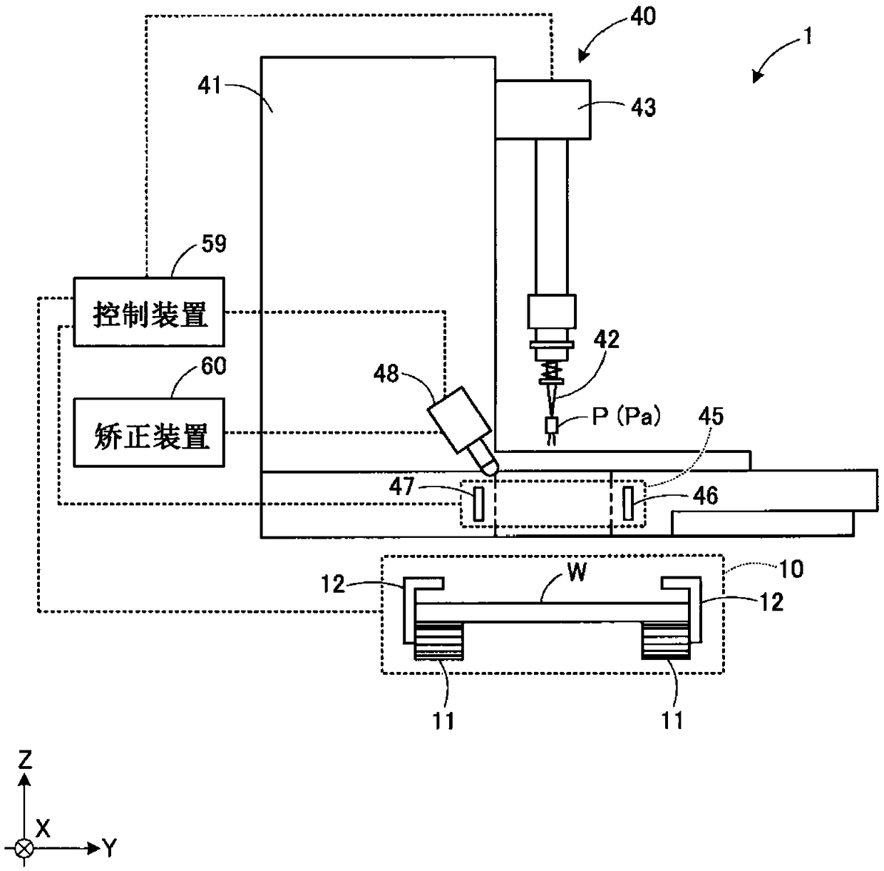
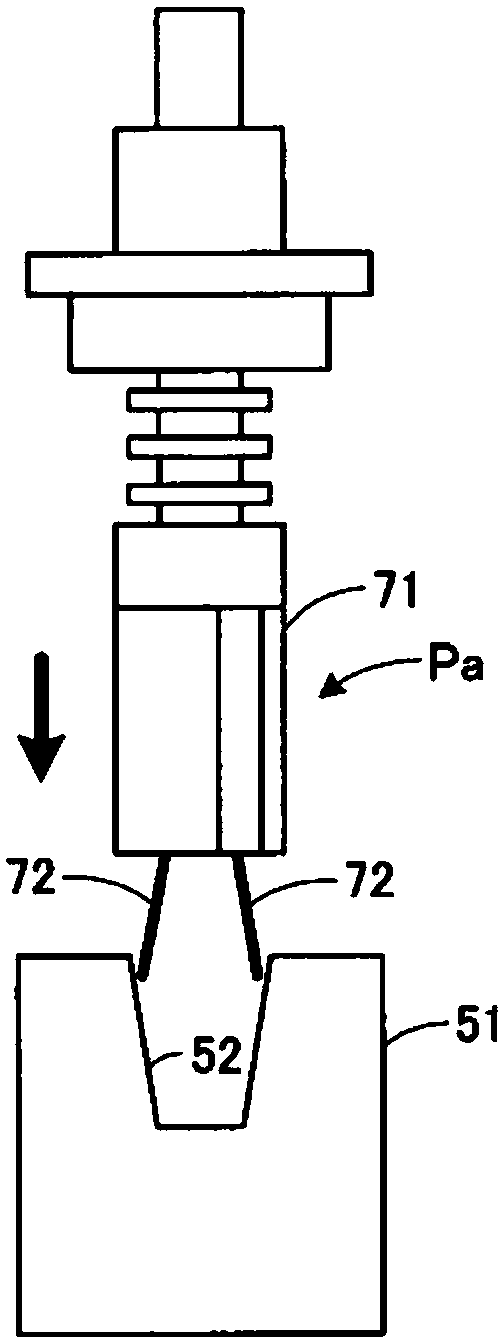
[0038] Hereinafter, the mounting device of the present embodiment will be described with reference to the drawings. figure 1 It is a schematic diagram showing the whole mounting apparatus of this embodiment. figure 2 It is a schematic diagram showing the periphery of the mounting head of this embodiment. Fig. 3 is a diagram showing an example of the correction operation of the lead member. In addition, the mounting apparatus of this embodiment is only an example, and can be changed suitably.

[0039] Such as figure 1 As shown, the mounting device 1 is configured to supply various parts P (refer to figure 2 ) It is mounted on a predetermined position of the substrate W by a pair of mounting heads 40. The mounting device 1 is provided with a substrate transport unit 10 that transports the substrate W in the X-axis direction. The substrate transport section 10 includes a pair of conveyor belts 11 that transport the substrate W and a pair of guide rails 12 that guide the transport...


PUM


Abstract

The invention provides a rectifying device, a mounting device, and a rectifying method, which reduce the re-trying times of rectifying actions and increase generation beat and reduce the risk of rectifying failure. The rectifying device conducts rectifying through pressing a lead part into the rectifying tool on the lead interval. The rectifying device comprises a measuring part which measures thelead interval of the lead part; a storing part which stores the press-in amount of the lead part relative to the rectifying tool; a rectifying part which presses the lead part into the rectifying tool with the press-in amount for rectifying; an adjusting part which adjusts the press-in amount under the situation that the rectified lead interval is outside of the allowing range; an updating part which updates the press-in amount under the situation that the rectified lead interval is within the allowing range, till the rectified lead interval is within the allowing range through the adjustingpart and the rectifying part. While adjusting the press-in amount, repetitive rectifying is conducted. Through the updating part, the press-in amount stored in the storing part is updated as the adjusted press-in amount.

Description

Technical field [0001] The present invention relates to a correction device, an installation device, and a correction method for correcting the lead spacing of a lead component. Background technique [0002] As a mounting device, a mounting device having a correction device is known that uses a correction tool to correct the lead spacing when the lead spacing of the lead member is outside the predetermined range (for example, refer to Patent Document 1). In the correction device described in Patent Document 1, the lead spacing of the lead member is measured by laser recognition, and concave and convex correction tools are used to distinguish between the lead spacing. Correction is performed by pressing a lead member with a wide lead spacing into a concave correction tool to narrow the lead spacing. By pressing a lead member with a narrow lead spacing into a convex correction tool, the lead spacing is widened for correction. . [0003] Patent Document 1: Japanese Patent Applicatio...

Claims


Application Information

Patent Timeline
IPC IPC(8): H05K13/04
CPCH05K13/04
Inventor 加藤慎也
Owner JUKI CORP
Learn More