

Hydraulic in-the-hole hammer with dual nozzles and combined valve
A technology of hydraulic down-the-hole hammer and compound valve, which is applied to the drilling driving device, drilling equipment, earth-moving drilling and mining in the wellbore, etc. Effect
- Summary
- Abstract
- Description
- Claims
- Application Information
AI Technical Summary
Problems solved by technology
Method used
Image

Examples
Embodiment Construction
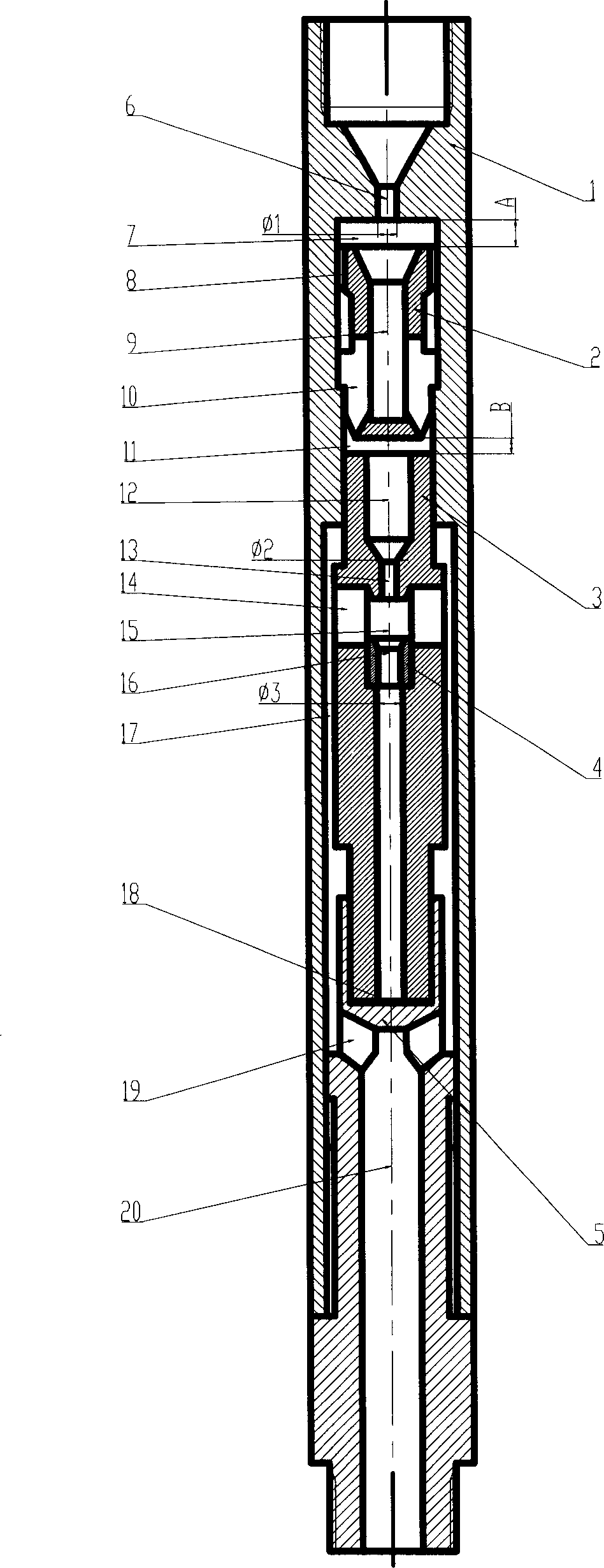
[0009] The double-nozzle composite valve type hydraulic down-the-hole hammer includes a casing 1, an upper valve 2, a hammer 3, a hammer bearing nozzle 4 and a lower joint 5. The upper center of the casing 1 is provided with an upper nozzle 6, which is facing the upper valve 2. The upper chamber 7 and the central hole 9 of the upper valve can use the jet formed by the high-speed movement of the liquid flow to generate a low-pressure effect at the upper chamber 7 of the upper valve; the outer diameter of the upper valve 2 forms a sliding fit with the inner diameter of this part of the shell 1, and the matching surface There is a longitudinal groove 8, the upper valve 2 can move freely up and down and has a limited position when moving downward, the movement stroke is A, and the value of A is 1-500 mm. The upper section of the hammer 3 forms a sliding fit with the shell 1, and the lower section forms a sliding fit with the inner hole of the upper section of the lower joint 5 to e...
PUM
| Property | Measurement | Unit |
|---|---|---|
| Diameter | aaaaa | aaaaa |
Abstract
Description
Claims
Application Information