Electromagnetic valve

A solenoid valve and magnetic technology, applied in the field of solenoid valves, can solve problems such as cost increase, and achieve the effect of correct positioning and stable positioning

Inactive Publication Date: 2003-04-02
SMC CORP
View PDF1 Cites 10 Cited by
  • Summary
  • Abstract
  • Description
  • Claims
  • Application Information

AI Technical Summary

Problems solved by technology

[0003] However, the above-mentioned conventional solenoid valve needs to have a complex structure in which the elastic force generated by the plate spring acts on the joint between the claw and the joint window when the solenoid part and the valve part are combin

Method used


Image

  • Electromagnetic valve
  • Electromagnetic valve
  • Electromagnetic valve

Examples


Embodiment Construction

[0018] Hereinafter, embodiments of the solenoid valve according to the present invention will be described in detail with reference to the drawings.

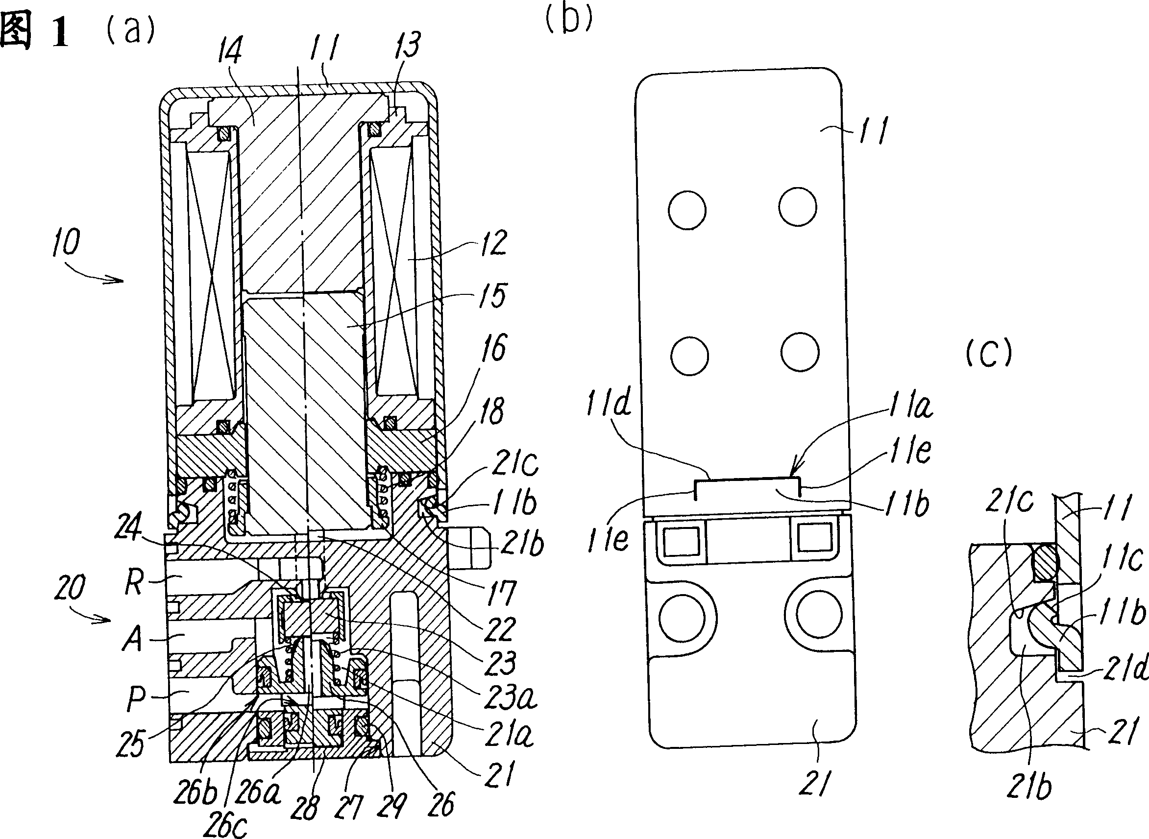
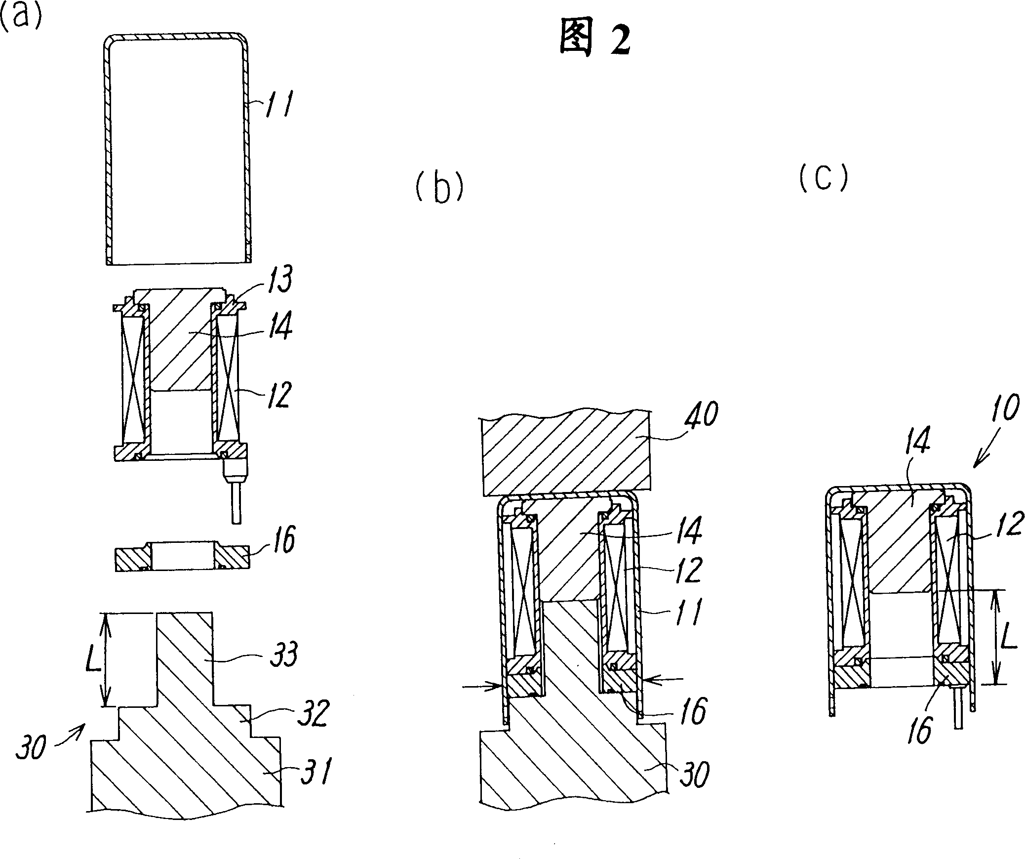
[0019] The solenoid valve shown in FIGS. 1( a ) to ( c ) is a solenoid valve according to the first embodiment, and includes a solenoid unit 10 and a valve unit 20 .

[0020] The solenoid part 10 is formed by a bobbin 13 on which a coil 12 is wound, a side wall having a substantially rectangular cross-section provided around the coil 12, and a segment end wall integrally formed with the side wall. : a magnetic box 11 with an opening at one end; a magnetic plate 16 disposed on one side of the opening of the above-mentioned magnetic box 11 in the above-mentioned bobbin 13; The central hole of the plate 16 and the coil frame 13 is slidably embedded with the inserted moving iron core 15 from one side of the magnetic plate 16; While being fitted and inserted into the center hole of the bobbin 13, the fixed iron core 14 (fixed magnet...


PUM


Abstract

The invention provides an electromagnetic valve where a high coupling strength between a valve portion and a solenoid portion can be secured simply at a low cost without large-sizing the solenoid portion. Recessed portions 21b which are positioned on one end side of a valve body 21 and whose inner wall faces formed by inclining faces 21c which incline from the one end side of the valve body 21 to the other end side towards its depth are provided on a valve body 21 side face positioned on one end side of the valve body 21 so as to be opposed to each other, while cuttings 11a for forming caulking pieces 11b are provided at positions corresponding to the recessed portions 21b on the side wall positioned on an opening side of a magnetic case 11, and the valve portion 20 and the solenoid portion 10 are coupled to each other in the state where they have been biased in directions in which they are fitted to each other by causing the caulking pieces 11b to abut on the inclining faces 21c of the recessed portions to caulk them in the recessed portions.

Description

technical field [0001] The present invention relates to a solenoid valve formed of a solenoid part and a valve part, and particularly relates to a solenoid valve having a structure suitable for downsizing. Background technique [0002] Conventionally, the above-mentioned solenoid valve is known as disclosed in Japanese Patent Application Laid-Open No. 06-071980. The solenoid valve consists of: a coil frame with a coil wound in a cover with an open end and a magnetic frame, a fixed iron core installed in the center hole of the coil frame, a magnetic plate arranged at one end side of the coil frame, and a slidable A moving iron core inserted into the center hole of the bobbin and the magnetic plate, and a solenoid part provided inside with a return spring for returning the moving iron core to an initial position, and a plurality of ports in the valve main body communicate with these ports The valve seat in the passage, and the valve part with the valve body built in to open a...

Claims


Application Information

Patent Timeline
IPC IPC(8): F16K31/06
CPCF16K31/0655F16K31/0627Y10T137/5987Y10T137/86622F16K31/06
Inventor 佐藤秀治麻生佳男芳村亲一松本拓实
Owner SMC CORP
Why Eureka
Try Eureka