Optical fiber dispersion compensation method and its device

A dispersion compensation and fiber dispersion technology, which is applied in the coupling of optical waveguides, electromagnetic wave transmission systems, electrical components, etc. length, the effect of improving the signal-to-noise ratio

Inactive Publication Date: 2003-04-23
HUAWEI TECH CO LTD
View PDF0 Cites 4 Cited by
  • Summary
  • Abstract
  • Description
  • Claims
  • Application Information

AI Technical Summary

Benefits of technology

The technology described in this patented solution improves how well an interference filter works when transmitting signals through different media without affecting their quality or reliability. It uses dispersive compensations that allow light waves from one medium enter another while being reflected off other surfaces before reaching its destination. This allows more efficient use of fibers and reduces costs associated therewith. Additionally, combining these techniques together helps reduce distortion caused during communication due to differences between materials used at each location.

Problems solved by technology

This patented technical problem addressed in this patents relates to improving the efficiency at transmitting light signals over long distances without requiring expensive equipment or complicated process steps for achieving desired properties such as improved bending loss characteristics due to reduced polarisation mode disperity.

Method used


Image

  • Optical fiber dispersion compensation method and its device
  • Optical fiber dispersion compensation method and its device
  • Optical fiber dispersion compensation method and its device

Examples


Embodiment Construction

[0020] The present invention will be described in detail below in conjunction with the accompanying drawings and embodiments.

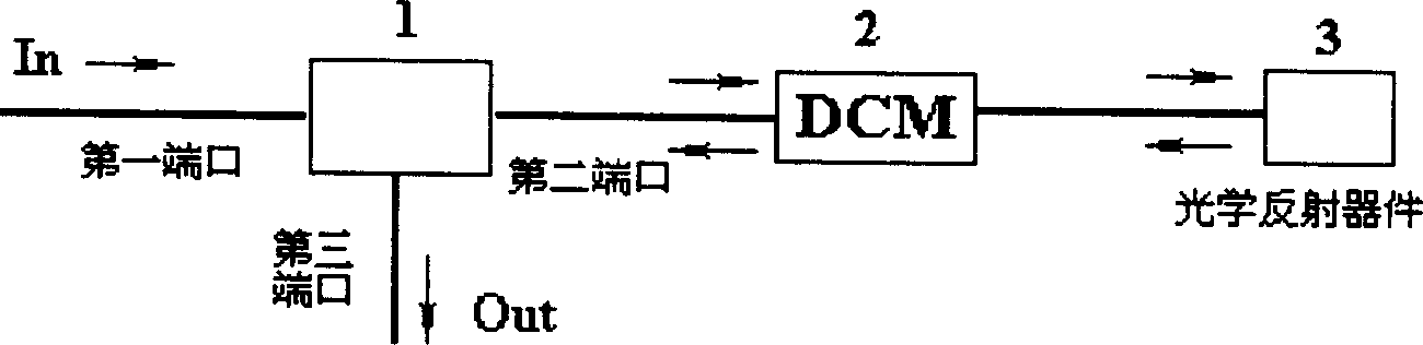
[0021] The overall structure of the dispersion compensation device proposed by the present invention is as follows: figure 1 shown. The dispersion compensation device includes a three-port irreversible optical device 1 , a dispersion compensation module (DCM) 2 and an optical reflection device 3 . The three-port irreversible optical device 1, the dispersion compensation module 2 and the optical reflection device 3 are sequentially connected, that is, the first port of the three-port irreversible optical device 1 is connected to the input transmission channel, and the output transmission channel is connected to the third port. The second port is connected to a dispersion compensation module (DCM) 2 followed by an optical reflection device 3 . The optical signal of the transmission channel is input from the first port of the three-port non-reciprocal ...


PUM


Abstract

The fibre dispersion compensation equipment includes dispersion compensation module, and includes a three-port irreversible optical device and an optical reflector device. Said three-port irreversible optical device, dispersion compensation module and ptical reflector device are sequentially connected, the optical signal is fed into first port of the above-mentioned three-port irrevesible opticaldevice, and outputted from second port and fed into dispersion compensation module to make dispersion compensation, then reflected by optical reflector device and fed into dispersion compensation module again to make secondary dispersion compensation, then said optical signal is fed into second port, and is outputted from third port, and fed into the dispersion compensation module, so that it cangreatly raise utilization rate of dispersion compensation optical fibre.

Description


Claims


Application Information

Patent Timeline
Owner HUAWEI TECH CO LTD
Why Eureka
Try Eureka