Floating coaxial connector

A coaxial connector, floating technology, applied in the direction of connection, two-part connection device, device to prevent wrong connection, etc., can solve the problem of affecting signal transmission, increasing the loss of electrical return loss, affecting high-frequency impedance matching, etc. question

Inactive Publication Date: 2003-05-14
张 祈福 +1
View PDF1 Cites 11 Cited by
  • Summary
  • Abstract
  • Description
  • Claims
  • Application Information

AI Technical Summary

Problems solved by technology

Due to the higher and higher requirements for receiving frequency, under the high-frequency transmission, the current transmitted from the rear contact to the scroll washer will rotate with the winding direction of the scroll washer, which will form an ...

Method used


Image

  • Floating coaxial connector
  • Floating coaxial connector
  • Floating coaxial connector

Examples


Embodiment Construction

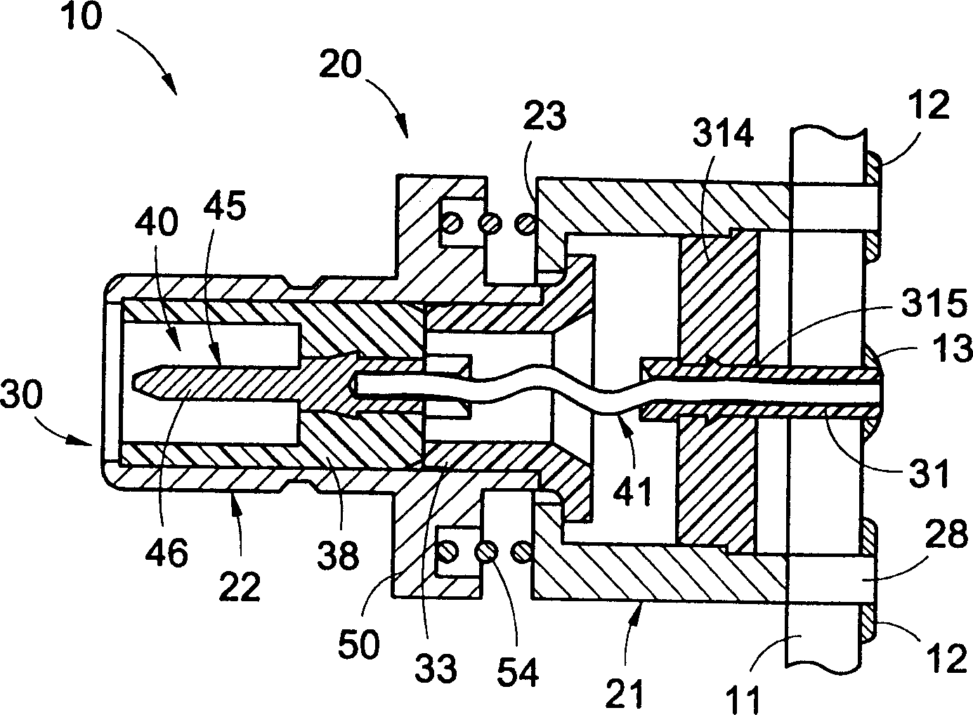
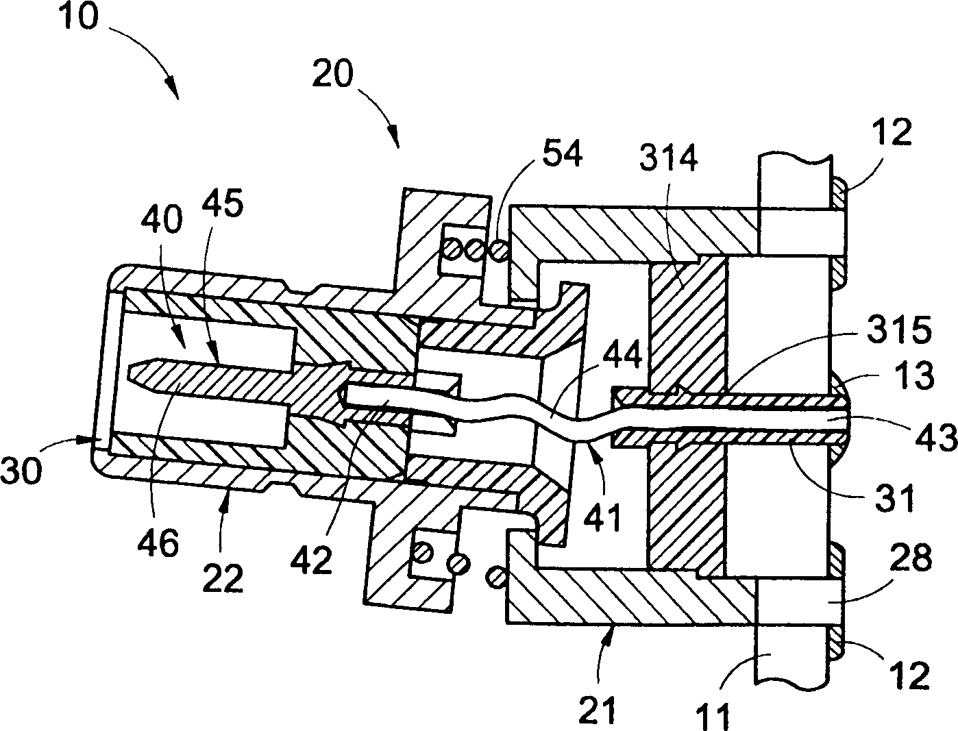
[0022] see figure 1 As shown, the floating coaxial connector 10 of the present invention includes a body assembly 20 , an insulating element assembly 30 , and a contact element assembly 40 . The coaxial connector 10 is fixed on a printed circuit board (PCB) 11 by soldering.

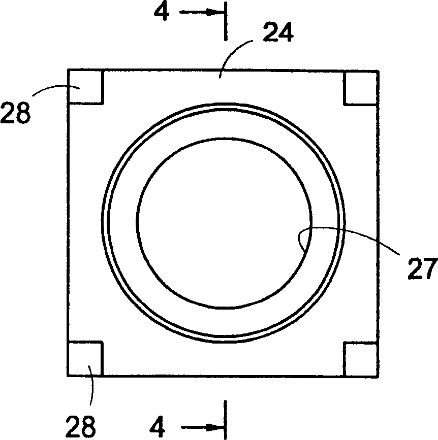
[0023] Body combination 20 comprises a rear body 21, such as image 3 and Figure 4 As shown, it has a front and rear face 23,24. A stepped cylindrical through hole 25 terminates internally in an annular flat bottom 26 which extends axially to the rear face 24 . The annular flat bottom 26 defines a borehole 27 .

[0024] The rear body 21 also includes four equidistantly spaced legs 28 protruding rearwardly from the rear face 24, which can be accommodated in small holes in a printed circuit board (PCB) 11 or a switchboard. The legs 28 can be connected to conductive pins on the PCB 11. Line 12 to facilitate grounding of body assembly 20 .

[0025] The body assembly 20 also includes a front body 22 whi...


PUM


Abstract

The floating coaxial connector includes front body, back body, connecting element and contact conductor capable of floating while the container is connected to other coaxial connector. The spring element between the front body and the back body makes the two contact reliably. The flexible connecting part in the connecting element allows the contact conductor to float coaxially to the back body for alignment.

Description

technical field [0001] The invention relates to a floating coaxial connector, the flexible connection part on the connecting element can allow the contact conductor to float to the rear body, and is opposite to the rear body, which can reduce the return loss of electrical appliances at high frequencies and solve the problem of Impedance matching problems at high frequencies. Background technique [0002] Known coaxial connectors are often mounted on switchboards or printed circuit boards (PCBs). Individual switchboards or PCBs are often mounted on machines that are not visually properly aligned prior to work. In particular, there are many types of telecommunications equipment that must be connected with multiple coaxial connectors. Thus, a PCB or power strip may use a row of coaxial connectors combined with a row of coaxial connectors on another PCB or power strip. One PCB or power strip must press against another PCB or power strip to simultaneously engage paired connect...

Claims


Application Information

Patent Timeline
IPC IPC(8): H01R13/64H01R24/44H01R24/50
Inventor 张祈福迈可·荷伦
Owner 张 祈福
Why Eureka
Try Eureka