Rotating disk style multi-position automative polisher

An automatic polishing, multi-station technology, used in polishing machine tools, manufacturing tools, metal processing equipment, etc., can solve the problems of operator health damage, heavy work and inefficiency, dust pollution, etc., to reduce processing costs and processing costs. Low, easy-to-handle effects

Inactive Publication Date: 2003-06-18
陈晓峰
View PDF0 Cites 26 Cited by
  • Summary
  • Abstract
  • Description
  • Claims
  • Application Information

AI Technical Summary

Benefits of technology

The technology described in this patented describes a system where it can simplify processes without requiring extensive modifications from previous steps. It allows workers to easily change their settings during different stages of operation while still being able to accurately measure how well they have done beforehand. Additionally, there may be special facilities needed only once every few hours instead of continuously running them throughout all day's operations. Overall, these improvements improve productivity and reduce manufacturing costs.

Problems solved by technology

This patented technical problem addressed by the present inventor relates to manual mechanic treatments for making metallized containers that are cost-effective but cause harmful environmental issues such as airborne particulate matter (PM) emissions from handling them during production processes.

Method used


Image

  • Rotating disk style multi-position automative polisher
  • Rotating disk style multi-position automative polisher
  • Rotating disk style multi-position automative polisher

Examples


Embodiment Construction

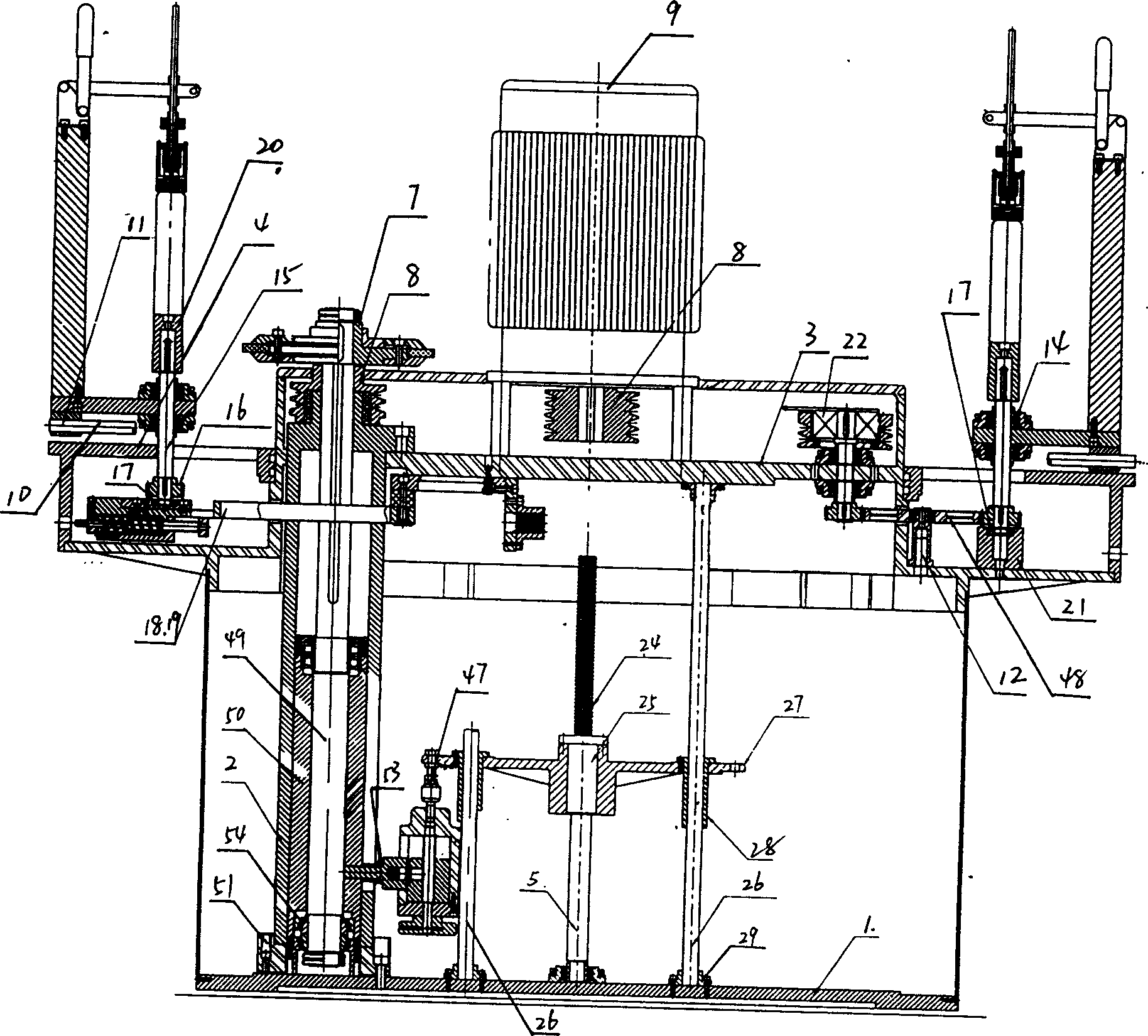
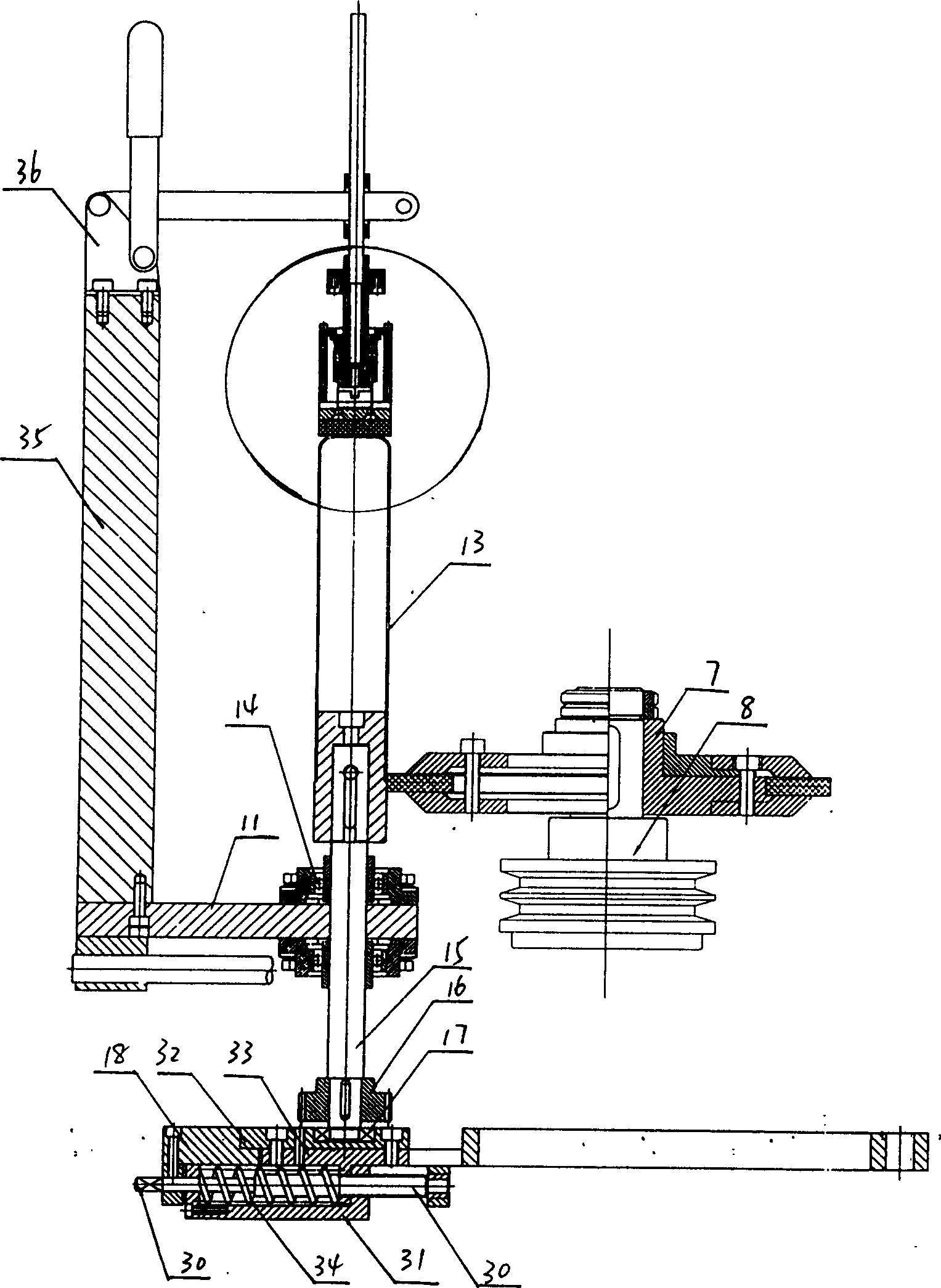
[0022] The present invention will be further described below in conjunction with embodiment. The three-layer structure adopted by the present invention is an important feature of this machine; this machine is composed of several large parts to form the skeleton of the whole machine; chassis 1, column 2, tray 3, turntable 4 and guide rail 5 supporting the Y-axis lifting movement. Their combination is roughly divided into three layers: the bottom chassis 1, the middle tray 3, and the high-level turntable 4. A column 2 is erected on the chassis 1, and the column 2 supports the tray 3, and the turntable 4 is placed on the tray 3. Between the chassis 1 and the pallet 3 is fixed a guide rail 5 supporting the Y-axis lifting movement. The chassis 1 of the bottom layer, the tray 3 of the middle layer and some columns 2 fixed between them are fixed. And the turntable 4 of high level is supported by pallet 3, can only turn a station successively by program setting under the drive of in...


PUM


Abstract

A turntable-type automatic polisher with multiple working positions is composed of base, vertical column, pallet, turntable, polishing wheel driven by main motor via belt and belt wheel and Y-axis motor via lifting and speed-varying unit, radiating tracks on the turntable, upper carriages moving on said tracks and with the fixer and clamper of workpiece, and lower carriages and their tracks on said pallet and driven by X-axis servo motor. Its advantages are high productivity and low cost.

Description


Claims


Application Information

Patent Timeline
Owner 陈晓峰
Why Eureka
Try Eureka