
Computer shell body

A shell and computer technology, applied in the direction of electrical digital data processing, instruments, digital data processing parts, etc., can solve the problems of high cost, many raw materials, cumbersome assembly process, etc., and achieve the effect of easy assembly and saving boards

Inactive Publication Date: 2003-07-02
HONG FU JIN PRECISION IND (SHENZHEN) CO LTD +1
View PDF2 Cites 1 Cited by
  • Summary
  • Abstract
  • Description
  • Claims
  • Application Information

AI Technical Summary

Problems solved by technology

However, the assembly process of the former is relatively cumbersome, while the structure of the inverted convex magnetic frame is not compact, and more raw materials are required for the manufacture of the two, resulting in higher costs

Method used


Image

  • Computer shell body
  • Computer shell body
  • Computer shell body

Examples


Embodiment Construction

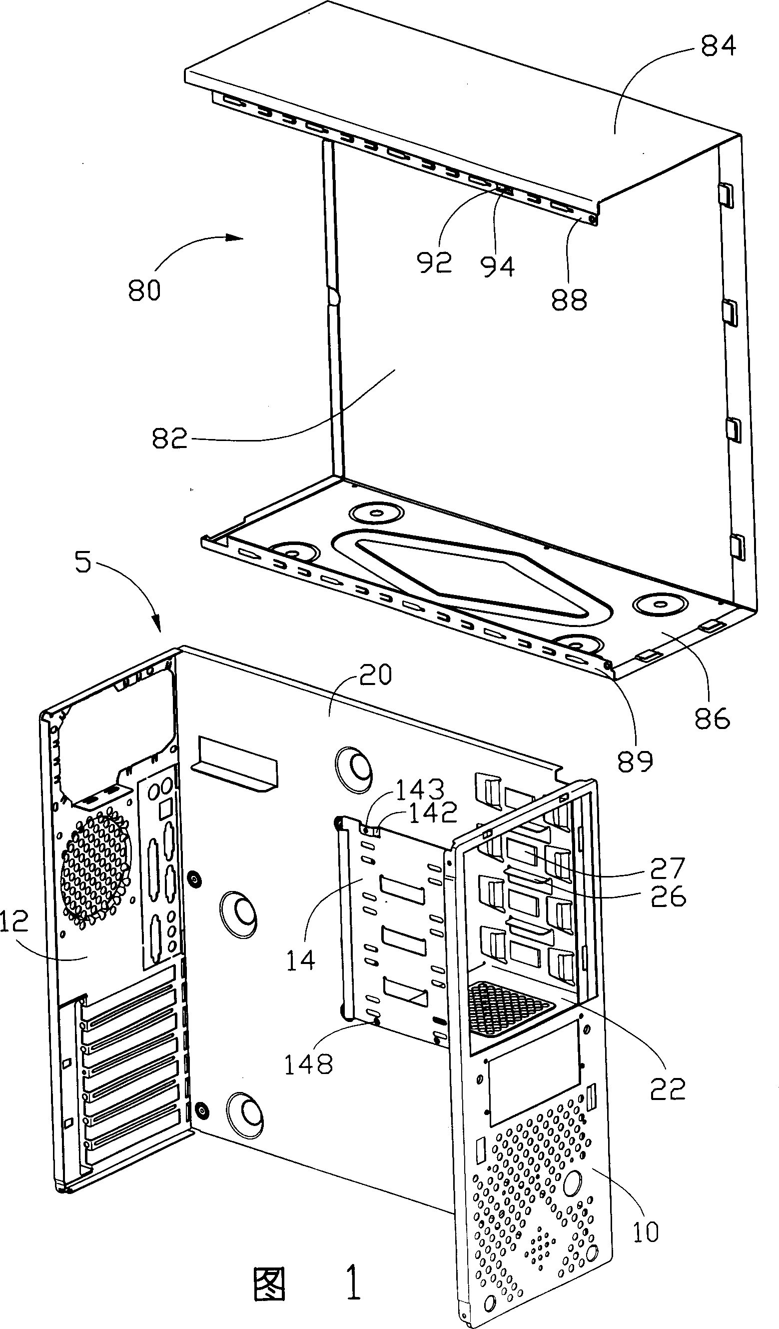
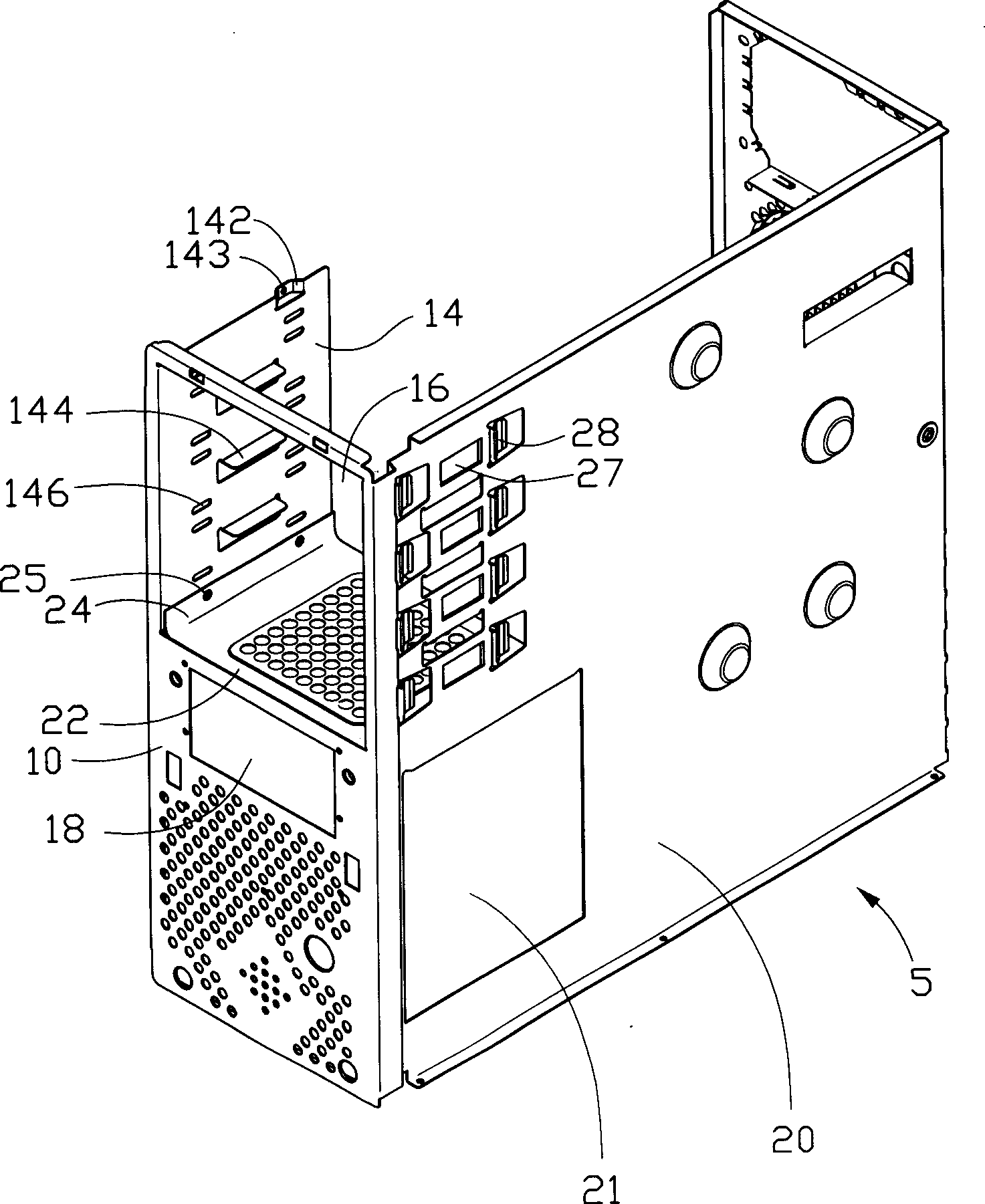
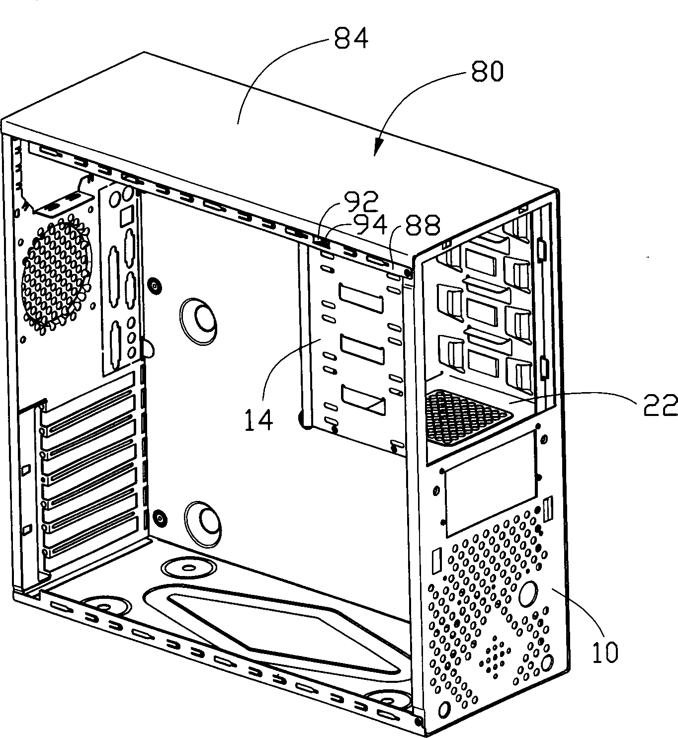
[0011] Please refer to Figure 1 to image 3 , The computer case of the present invention includes a base 5 and an outer cover 80 .

[0012] The base 5 is integrally stamped from a metal plate, and includes a front plate 10 , a rear plate 12 and a supporting plate 20 . The top of the front plate 10 bends a vertical wall 14 parallel to the load plate 20 vertically inwardly to form a larger opening 16, and the lower portion of the larger opening 16 also offers a smaller opening 18. On the vertical wall 14 A protruding piece 142 is bent outward at the edge, and a through hole 143 is provided on it, and a plurality of parallel bearing pieces 144 are vertically bent inwardly on the vertical wall 14, and two rows are respectively arranged along the two sides of the bearing piece 144. The locking hole 146 and the lower edge of the vertical wall 14 are also provided with two through holes 148 .

[0013] The carrier plate 20 also bends vertically inwards a horizontal plate 22 perpendi...


PUM


Abstract

A computer casing is composed of a base and an external cover. Said base consists of a front plate with a vertical wall bent inward to form a window, a bearing plate with a horizontal plate bent inward and a back plate. Said vertical wall has a projected plate and two through holes near the bottom. Said horizontal plate has a locking part bent upward with two through holes relative to said through holes on vertical wall. Said external cover has an inward projected plate for locking it with the projected plate of vertical wall to prevent deformation of vertical wall.

Description

【Technical field】 [0001] The invention relates to a computer casing, in particular to a computer casing with simple structure, low cost and convenient assembly. 【Background technique】 [0002] A general computer case usually includes components such as a front plate, a rear plate, a load plate, a magnetic frame, an outer cover, and a side plate, and one or more magnetic frames are installed in the computer case to accommodate and fix components such as hard and soft components. Data access devices such as hard drives and optical drives. [0003] The magnetic frame of a general computer case is usually a split type, which is composed of at least two magnetic frames, one large and one small, which are respectively fixed at the rear of the opening on the front panel to install data access devices of different sizes. device, and these magnetic racks are installed in the base after being combined with pull studs or corresponding buckle structures, or directly locked in the base ...

Claims


Application Information

Patent Timeline
Patent Type & Authority Applications(China)
IPC IPC(8): G06F1/16
Inventor 陈允隆
Owner HONG FU JIN PRECISION IND (SHENZHEN) CO LTD
Learn More