Overlay decorating plate

A decorative panel and covering technology, applied in covering/lining, floors, buildings, etc., can solve the problems of complex milling process, difficulty in improving processing efficiency, poor waterproof and dustproof effect at the joints of floor boards, etc., to achieve good anti-corrosion Dust and waterproof effect, save labor intensity, improve the effect of laying efficiency

Active Publication Date: 2013-09-11
CHANGZHOU BEMATE HOME TECH CO LTD
View PDF7 Cites 0 Cited by
  • Summary
  • Abstract
  • Description
  • Claims
  • Application Information

AI Technical Summary

Problems solved by technology

However, the installation of this kind of floorboard requires a large space for activities and has high requirements for the installation occasion. It is also inconvenient to repair or remove it after installation.
[0004] In addition, the manufacturing method of the above-mentioned floor boards also has certain limitations. Since these floor boards all have a protruding tongue-shaped structure, when the board is opened, the board can only be opened perpendicular to the board surface. Connect small plates with structural dimensions, and then mill the connecting parts to form tongues and grooves. The size of these connecting parts increases the amount of plates used. At the same time, due to the large difference in shape between the finished product and the small plates, the milling process is more complicated and wasteful. It is also difficult to improve the processing efficiency, and the waterproof and dustproof effect of the junction of the two floor boards is not good.

Method used


Image

  • Overlay decorating plate
  • Overlay decorating plate
  • Overlay decorating plate

Examples


Embodiment Construction

[0040] In order to make the above-mentioned purposes, features and advantages of the present invention more obvious and understandable, the preferred embodiments of the present invention will be specifically cited below, together with the accompanying drawings, for a detailed description as follows:

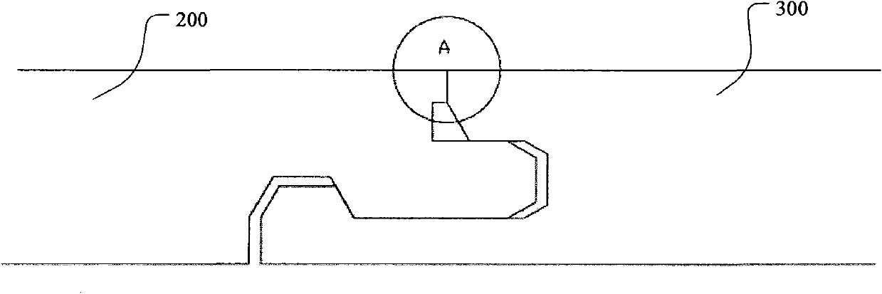
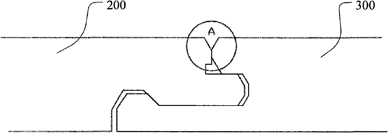
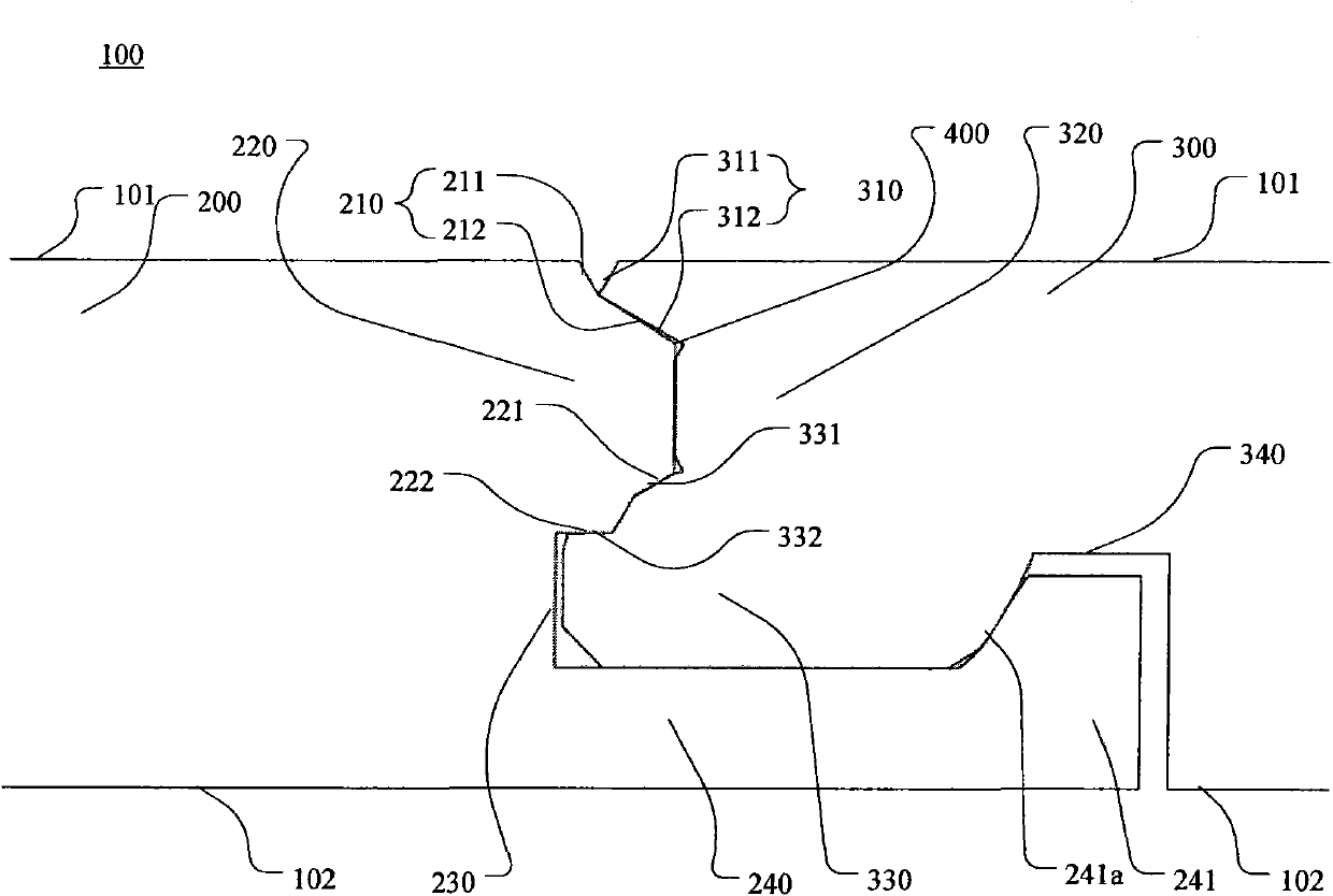
[0041] Such as image 3 As shown, a covered decorative board includes a board body 100 with a predetermined thickness, the upper surface of the board body 100 is a surface layer 101, the lower surface of the board body 100 is a bottom layer 102, and the board body 100 At least one edge is provided with an upward connecting portion 300, and the other edge opposite to this edge is provided with a downward connecting portion 200, and the two covering decorative panels can pass through the upward connecting portion 300 and the downward connecting portion 200. connected.

[0042]Wherein, the downward connecting portion 200 at least includes: a first slope 210, the first slope 210 inc...


PUM


Abstract

The invention discloses an overlay decorating plate, which comprises a plate body, wherein the upper surface of the plate body is a surface layer, the lower surface of the plate body is a bottom layer, at least one edge of the plate body is provided with an upward connecting part, the other edge opposite to the edge is provided with a downward connecting part, and two overlay decorating plates are mutually connected through the upward connecting part and the downward connecting part; the downward connecting part at least comprises a first inclined plane, a first tenon and a first groove; the upward connecting part at least comprises a second inclined plane, a second groove and a second tenon; and when the two overlay decorating plates are connected with each other, the first tenon is in butt joint with the second groove, the first groove is in butt joint with the second tenon, an eudipleural groove is formed between a first upper surface and a second upper surface, and the first inclined plane and the second inclined plane are in a three-dimensional butt joint state. The overlay decorating plate disclosed by the invention has a simple structure, is convenient to splice, and is material-saving.

Description

【Technical field】 [0001] The invention relates to a decorative panel, in particular to a covering decorative panel that can be spliced ​​together. 【Background technique】 [0002] In the covered decorative panel industry, the floor is the main representative. Its existing splicing method is edge parallel butt joint, that is, after the floor is spliced, the edges of the panels are in a parallel butt joint state, including flat panel, three-dimensional chute, and NCD cornerless processing technology. And the three-dimensional inversion technology of grinding and pressing are all parallel butt joint processing technologies. When the construction work surface is not smooth enough or the link part is loose, the prerequisite for parallel butt collision cannot be achieved. There is a common phenomenon that is caused now, the floor slits form visible gaps, forming many hidden dangers such as sewage and water ingress, which seriously affects the decorative aesthetic effect and normal ...

Claims


Application Information

Patent Timeline
Patent Type & Authority Patents(China)
IPC IPC(8): E04F15/02E04F13/076
Inventor 陈明星张国洪吴风昌
Owner CHANGZHOU BEMATE HOME TECH CO LTD
Why Eureka
Try Eureka