Joint structure and method for building structural component unit

A joint method and technology for building components, which are applied in the direction of building structure and construction, can solve the problems of offset of the column connecting part, inconvenient bolt tightening operation, and inconvenient confirmation of the bolt tightening state, so as to achieve stable joint state, The effect of convenient connection work

Inactive Publication Date: 2003-07-09
KOMATSU HOUSE
View PDF0 Cites 11 Cited by
  • Summary
  • Abstract
  • Description
  • Claims
  • Application Information

AI Technical Summary

Problems solved by technology

From the perspective of the former prior art, since the connection is performed inside the column of the superstructure member with a long-sized bolt tightening tool, the confirmation of the tightened state of the bolt cannot be easily performed.
In addition, because there are spiral guide rails and tool guides inside the column, it is not convenient to use a bolt tightening tool for bolt tightening.
Therefore, the latter method of connecting relative

Method used


Image

  • Joint structure and method for building structural component unit
  • Joint structure and method for building structural component unit
  • Joint structure and method for building structural component unit

Examples


Embodiment 1

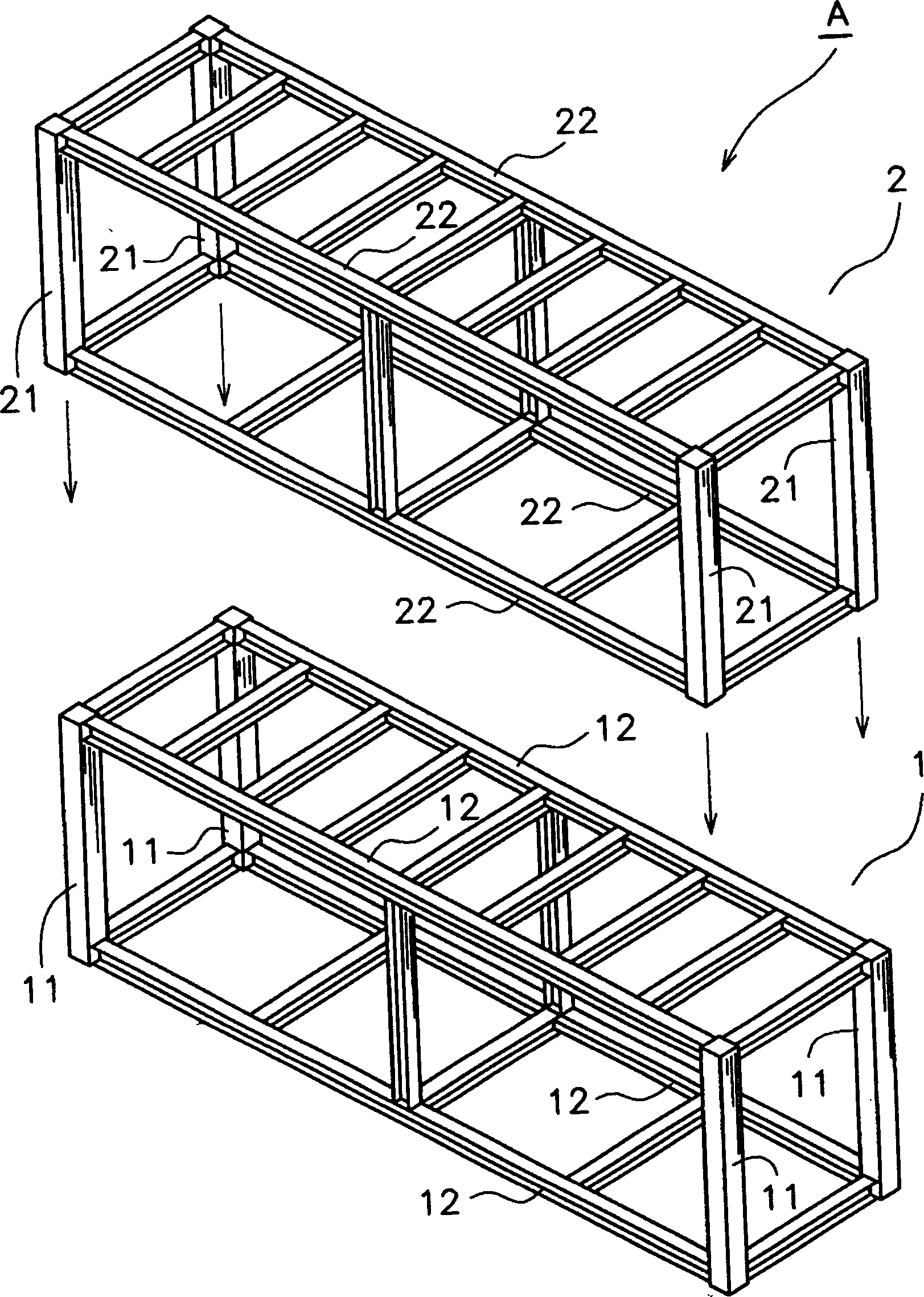
[0018] Embodiment 1, the present invention will be described below according to the accompanying drawings. Such as figure 1 As shown, 1 and 2 are building components that constitute units, and the present invention relates to the invention of the connection structure and connection method of building components 1 and 2. On the lower building component 1, the upper building component 2 is superimposed, and the unit room A with 2 or 3 floors is formed after the two are joined. The building elements 1, 2 are composed of a plurality of columns 11, 21 and beams 12, 22. In this embodiment, when the above-mentioned building components 1 and 2 are stacked, the upper end of the lower column 11 constituting the lower building component is connected to the lower end of the upper column 21 constituting the upper building component 2 .

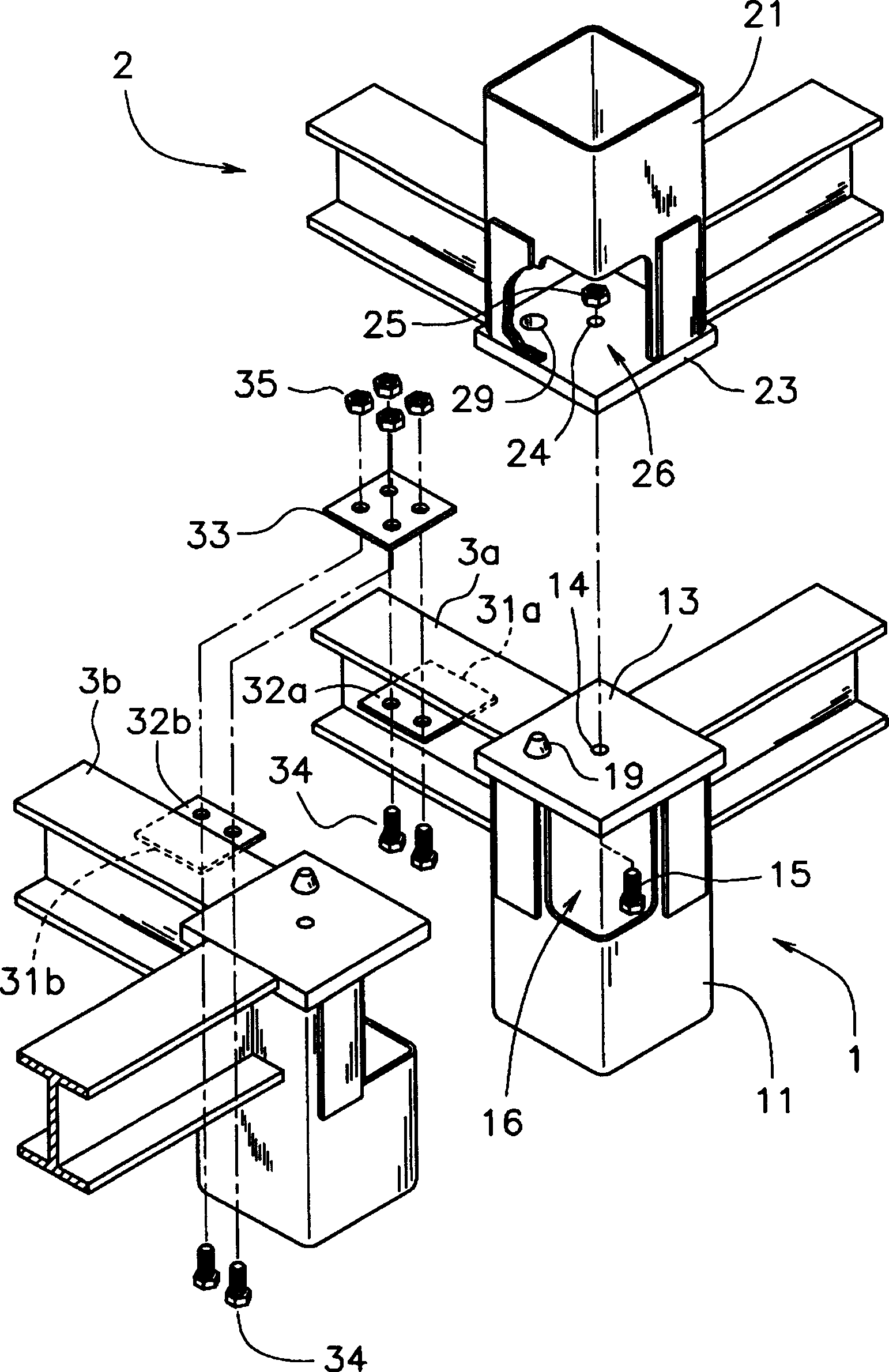
[0019] Such as figure 2 As shown, the column 11 for the lower layer and the column 21 for the upper layer in this embodiment are composed of a cylindr...

Embodiment 2

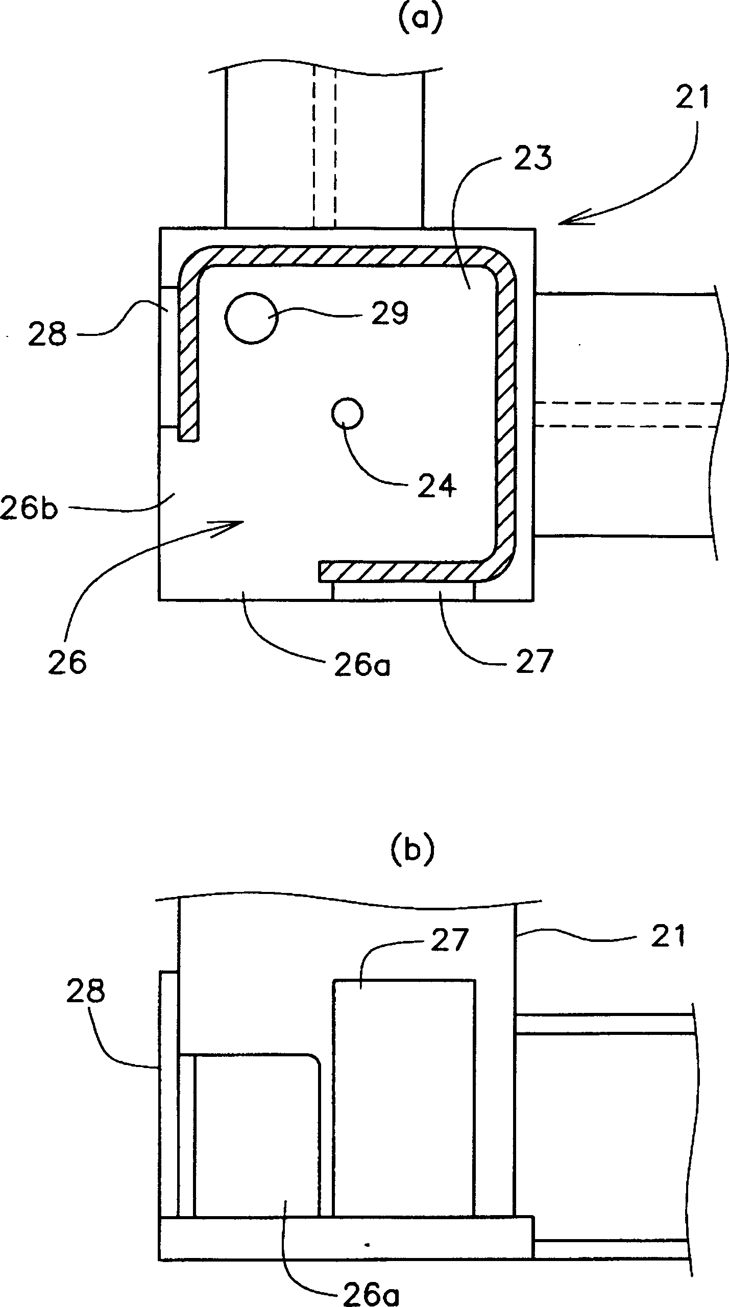
[0030] Embodiment 2, the second embodiment of the connection structure will be described below. Such as Figure 5 As shown, this is a structure in which the lower column 111 constituting the lower building member 101 is connected to the upper building member 102, and is roughly the same as the first embodiment. The difference is that the upper end of the column 111 for the lower layer in this embodiment is provided with a horizontal joint surface 113 , and the center of this surface is provided with a protruding bolt external thread portion 115 along the length direction of the column 111 . Furthermore, no notch is provided on the side surface of the column 111 for the lower floor, and of course there is no reinforcing plate. On the other hand, the upper column 121 constituting the upper building member 102 is provided with a notch 126 in the same structure as the first embodiment, and reinforcing plates 127, 128 are provided on both sides thereof.

[0031] When the superstr...


PUM


Abstract

The joint structure and method for building structural component unit of the present invention is about invention of building structural component joint structure. The present invention is a joint structure for upper story building structural component and lower story building structural component. The lower story column top end of the lower story building structural component and the upper story column lower end of the upper story building structural component are disposed with level joint surfaces for jointing the two components. The center parts of the joint surfaces are disposed with through holes. The column body surfaces adjacent to the upper and lower column joint surfaces are cut with gaps. Bolts are inserted into the through holes and fastened when docking the level surfaces. The advantage of the present invention is that bolts and nuts can be put in the inner side of the columns through the gaps adjacent to the joint ends of the columns by using the joint structure of the present invention, and the joint work for building structural components is facilitated; the present invention can position the joint status according requirement and makes joint stable; and the joint work is also made very convenient.

Description

technical field [0001] The joint structure and joint method of building component units of the present invention are inventions related to the connection structure of building components. In particular, it refers to the structure and method of connecting the upper and lower building components with columns in the building components composed of beams and columns. Background technique [0002] In the past, the technical example of connecting the upper and lower building structures with columns is the technology disclosed in the Patent Publication No. 2001-254445, that is, a long-sized bolt tightening tool is inserted from the upper end of the superstructure component column, and the above-mentioned column is passed through. Tighten the bolts at the lower end of the column to achieve the purpose of connecting with the upper end of the lower building components. In addition, the bolt-tightening tool can pass through the center of the column because of the helical guide rail in...

Claims


Application Information

Patent Timeline
IPC IPC(8): E04B1/348E04B1/38E04B1/48
Inventor 重茂宗夫杉本嘉一
Owner KOMATSU HOUSE
Why Eureka
Try Eureka