Optical communication module and its optical coupling assembly method

An optical communication and optical coupling technology, applied in the field of optical communication modules, can solve the problems of improper operation alignment, failure of smooth conversion of photoelectric signals, defective products, etc.

Active Publication Date: 2016-03-02
DELTA ELECTRONICS INC
View PDF6 Cites 0 Cited by
  • Summary
  • Abstract
  • Description
  • Claims
  • Application Information

AI Technical Summary

Problems solved by technology

[0005] However, in this conventional optical cable connector assembly structure 1, since the alignment frame 11, the lens carrier 10, the circuit board 12, and the optical cable connector 15 are assembled in a mechanical structural alignment, if one of the components During the process of plugging and assembling, interference from external forces or improper operation and alignment can easily cause errors in alignment assembly, and since the photoelectric conversion of the optical cable connector assembly structure 1 requires precise optical alignment, if any A little error will cause the photoelectric signal to fail to convert smoothly, which will lead to problems such as defective products or product damage

Method used


Image

  • Optical communication module and its optical coupling assembly method
  • Optical communication module and its optical coupling assembly method
  • Optical communication module and its optical coupling assembly method

Examples


Embodiment Construction

[0097] Some typical embodiments embodying the features and advantages of the present invention will be described in detail in the description in the following paragraphs. It should be understood that the present invention is capable of various changes in different ways without departing from the scope of the present invention, and that the description and drawings therein are illustrative in nature rather than limiting the present invention.

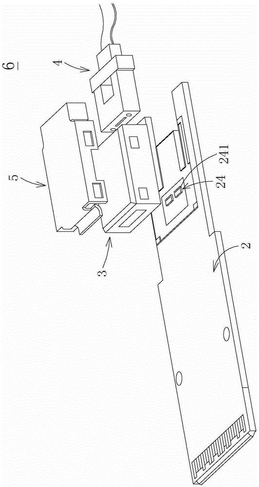
[0098] see figure 2 , which is a schematic structural diagram of an optical communication module in a preferred embodiment of the present invention. As shown in the figure, the optical communication module 6 of the present invention is mainly composed of a substrate 2, a lens coupling carrier 3 and a sleeve 4. In some embodiments, the optical communication module 6 may also include a clamp 5, but not with This is the limit. Wherein, the substrate 2 has at least two transceiver light-emitting chips 24, and each transceiver light-emitti...


PUM


Abstract

The invention provides an optical communication module which comprises a substrate, a lens light coupling carrier and a sleeve. The substrate is provided with at least two light transmitting and receiving chips, the chips are provided with a plurality of photoelectric units, and each photoelectric unit has a positioning characteristic. The lens light coupling carrier has a frame and a lens array, and the lens array contains a plurality of lens units. The sleeve and the lens light coupling carrier are assembled together. Each photoelectric unit of the substrate corresponds to one lens unit of the lens light coupling carrier. When the lens light coupling carrier and the substrate are assembled, the photoelectric units and the lens units can be passively positioned and aligned according to the positioning characteristics of the photoelectric units so as to enable the lens light coupling carrier and the substrate to be precisely aligned with each other, and then a precise optical communication path is formed through assembly of the sleeve and the lens light coupling carrier.

Description

technical field [0001] The invention relates to an optical communication module, in particular to an optical communication module with a lens optical coupling carrier and an optical coupling assembly method thereof. Background technique [0002] With the rapid development of information technology, the demand for information communication and transmission is increasing, and the demand for data transmission speed and bandwidth is also increasing. The optical communication industry of transmission also develops vigorously thereupon. [0003] In the optical communication industry, since signal communication mainly converts optical signals into electrical signals, or converts electrical signals into optical signals, and then transmits the converted optical / or electrical signals through optical fibers, among them, optical transmission In the path, if the alignment of a link is not accurate enough, there may be errors in signal transmission and conversion, which will lead to prob...

Claims


Application Information

Patent Timeline
Patent Type & Authority Patents(China)
IPC IPC(8): G02B6/43
Inventor 陈秀萍游宏彬翁佳恺
Owner DELTA ELECTRONICS INC
Why Eureka
Try Eureka