Winding mould and deflection coil

A deflecting coil and winding technology, which is applied in the field of deflection coils and line product rate adjustment slots, can solve problems such as changes in line product rate and unimproved picture quality.

Inactive Publication Date: 2003-07-09
SAMSUNG ELECTRO MECHANICS CO LTD
View PDF0 Cites 0 Cited by
  • Summary
  • Abstract
  • Description
  • Claims
  • Application Information

AI Technical Summary

Problems solved by technology

[0025] As mentioned above, in order to solve the problems in the conventional technology, the winding rotation speed of the deflection yoke is changed or local welding is performed. However, this structure only improves the characteristics of the desired part locally, resulting in an overall line product. Rate changes, ultimately did not improve the picture quality, still become a serious problem

Method used


Image

  • Winding mould and deflection coil
  • Winding mould and deflection coil
  • Winding mould and deflection coil

Examples


Embodiment Construction

[0048] Hereinafter, a correct example of the winding die of the present invention and a deflection yoke produced therefrom will be described in detail with reference to the drawings. The same symbols are used for the same elements in different drawings. Furthermore, the invention is not limited to the examples described.

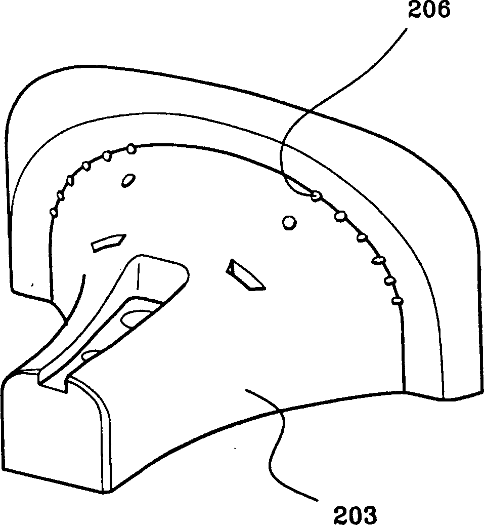
[0049] Figure 8 is an oblique view illustrating a correct example of an A-type wire winding die according to the present invention. In the center of the above-mentioned wire winding mold, there is a wire winding surface 3 with a certain degree of curvature. In the above-mentioned wire winding surface 3, in order to increase the line area ratio of the winding lines, any part of the overall surface has a certain degree of protrusion according to the vertical direction of the winding lines. The lead groove 7.

[0050] In addition, guide surfaces 4 having curved surfaces and inclinations are formed on both sides of the winding surface 3 . In the inner side ...


PUM


Abstract

Disclosed is a deflection yoke for improve a screen quality, including a coiling density adjustment groove formed along a vertical direction of a coil by way of increasing the coiling density at an arbitrary portion of the electric field at the internal side of the deflection coil. To this end, a winding frame for winding coil around the deflection yoke, having a curvature of a designated shape at the center is provided, in which the winding frame includes a wire position guide that is projected as much as a designated width to a vertical direction of a coil to be wounded around an arbitrary portion of the internal electric field for increasing a coiling density.

Description

technical field [0001] The invention discloses a deflection coil, in particular a deflection coil using a winding mold. The present invention relates to a line area ratio adjustment groove formed in any part of the overall area of ​​the inner surface of the deflection yoke according to the adjustment direction of the coil in order to improve the line area ratio of the deflection yoke (or the Q value of the deflection yoke), and for the above content, in A wire groove structure is formed in the wire winding die of the wire reel that winds the deflection yoke. [0002] That is, the structure of the winding die is improved for winding the wire in the deflection yoke, thereby improving the characteristics of the deflection yoke manufactured using this structure, and achieving the purpose of improving the characteristics of the deflection yoke as a whole. Background technique [0003] Figure 1 is a sectional view illustrating the structure of a general deflection yoke. As show...

Claims


Application Information

Patent Timeline
Patent Type & Authority Applications(China)
IPC IPC(8): H01J9/236H01F7/00H01J29/76H01J29/82
CPCH01J2229/7038H01J29/826H01J29/762H01J9/236
Inventor 金炅守南宫容吉李青纹黄硕焕
Owner SAMSUNG ELECTRO MECHANICS CO LTD
Why Eureka
Try Eureka