Primary-side controlled flyback power converter

a flyback power converter and control technology, applied in the direction of electric variable regulation, process and machine control, instruments, etc., can solve the problems of high power consumption, large size, and significant increase in the power consumption of the sense resistor of the power converter, so as to reduce the cost of the power supply and the size

Inactive Publication Date: 2005-02-08
FAIRCHILD TAIWAN
View PDF6 Cites 239 Cited by
  • Summary
  • Abstract
  • Description
  • Claims
  • Application Information

AI Technical Summary

Benefits of technology

A principal object of the present invention is to provide a flyback power converter under primary-side PWM control. The flyback power converter according to the present invention supplies a well-regulated constant voltage and constant current output. However, unlike prior-art PWM controllers, it does not require a secondary-side feedback circuit or an optical-coupler. This enables the device count, the size, and the cost of the power supply to be reduced.
Another feature of the flyback power converter according to the present invention is an offset current source. The offset current source is used to compensate for the temperature dependence of the output rectifier. This allows the PWM controller to be supplied with a more accurate feedback signal. The offset current source of the PWM controller pulls an offset current from an input of the double sample amplifier in response to the operating temperature of the flyback power converter. The offset current will produce a voltage drop across a detection resistor to compensate for voltage variations across the output rectifier.

Problems solved by technology

One drawback of this circuit is its large size, due to the need for an optical-coupler and a secondary feedback-control circuit.
Another drawback of this flyback power converter is high power consumption.
The current-sense resistor significantly increases the power consumption of the power converter.
One drawback of this prior-art invention is that the feedback control voltage is sensed from a high voltage source.
This method results in a loss of accuracy, and it increases the cost of the controller.
Another drawback is that the voltage drop of the output rectifier is not compensated for.
The drawback of this prior-art is that the optical-coupler and the secondary feedback circuit are still required for loop control.
One principal drawback of these two prior-arts is inaccurate feedback control.
However, this reflected voltage signal is not directly proportional to the output voltage, because of the spike voltage generated by the leakage inductance of the transformer.
Furthermore, the voltage drop of the output rectifier is not compensated for in the feedback loop.
When load changes occur, this problem will introduce additional distortion into the output voltage.
Another drawback of these two prior-art inventions is high power consumption.
However, the resistor in the filter burns the majority of the reflected power, even if the power consumption required for PWM control is low.
Therefore, the power consumption of the power supply is high.

Method used


Image

  • Primary-side controlled flyback power converter
  • Primary-side controlled flyback power converter
  • Primary-side controlled flyback power converter

Examples


Embodiment Construction

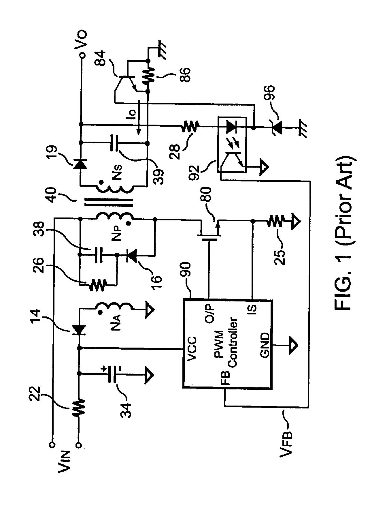
FIG. 1 shows a traditional flyback power converter. A capacitor 34 is connected to a PWM controller 90 and is charged via a resistor 22. The PWM controller 90 will be started up once its supply voltage VCC is higher than a start-threshold voltage. When the PWM controller 90 starts to operate, it will output a PWM signal to drive a switching transistor 80 and a transformer 40. Meanwhile, an auxiliary winding NA of the transformer 40 supplies the supply voltage VCC via a rectifier 14. A current-sense resistor 25 converts a switching current of the transformer 40 into a voltage signal for PWM control and over-power protection. An output of an optical-coupler 92 supplies a feedback voltage VFB.

The output voltage VO and the Zener voltage of a Zener diode 96 drive an input of the optical-coupler 92 via a resistor 28 to form the feedback loop. The magnitude of the feedback voltage VFB of the PWM controller 90 determines the on-time (TON) of the PWM signal and regulates the output power. A ...


PUM


Abstract

The present invention provides a primary-side flyback power converter that supplies a constant voltage output and a constant current output. To generate a well-regulated output voltage under varying load conditions, a PWM controller is included in the power converter in order to generate a PWM signal controlling a switching transistor in response to a flyback voltage sampled from a first primary winding of the power supply transformer. Several improvements are included in this present invention to overcome the disadvantages of prior-art flyback power converters. Firstly, the flyback energy of the first primary winding is used as a DC power source for the PWM controller in order to reduce power consumption. A double sample amplifier samples the flyback voltage just before the transformer current drops to zero. Moreover, an offset current is pulled from a detection input of the double sample amplifier in order to generate a more accurate DC output voltage. The offset current is generated in response to the temperature in order to compensate for temperature-induced voltage fluctuations across the output rectifier. Ultimately, in order to maintain a constant output current, the PWM controller modulates the switching frequency in response to the output voltage.

Description

BACKGROUNDING OF THE INVENTION1. Field of InventionThe present invention relates to a switching mode power converter and more particularly relates to a flyback power converter.2. Description of Related ArtA flyback power converter typically includes a PWM controller, a power MOSFET (Metal Oxide Semiconductor Field Effect Transistor), a transformer, and a feedback-control circuit. The purpose of the feedback-control circuit is to sense the output voltage and / or the output current of the secondary-side of the power supply, and to supply a feedback signal to the PWM controller through an isolated device such as an optical-coupler.FIG. 1 shows a traditional flyback power converter. Although this circuit is able to regulate the output voltage and output current, it has several drawbacks. One drawback of this circuit is its large size, due to the need for an optical-coupler and a secondary feedback-control circuit. Another drawback of this flyback power converter is high power consumption...

Claims


Application Information

Patent Timeline
Patent Type & Authority Patents(United States)
IPC IPC(8): H02M7/00H02M3/335H02M3/24
CPCH02M3/33507H02M1/32Y02B70/16H02M2001/0032H02M2001/0041H02M2001/0006H02M1/0006H02M1/0032H02M1/0041Y02B70/10
Inventor YANG, TA-YUNGLIN, JENN-YU G.CHEN, CHERN-LIN
Owner FAIRCHILD TAIWAN
Why Eureka
Try Eureka