Thin film write head with interlaced coil winding and method of fabrication

a technology of interlaced coils and write heads, which is applied in the construction of head windings, instruments, data recording, etc., can solve the problems of limiting the minimum dimension of the winding, and reducing the overall stack heigh

Inactive Publication Date: 2002-10-15
WESTERN DIGITAL TECH INC
View PDF10 Cites 237 Cited by
  • Summary
  • Abstract
  • Description
  • Claims
  • Application Information

AI Technical Summary

Problems solved by technology

One problem with the above process is that it limits the minimum dimension of the winding.
Another drawback of the above process and structure is that it produces a coil structure with a high overall stack height.
Also, because cured photoresist is difficult to form in extremely thin layers, the cured photoresist insulation typically formed under the conductor winding significantly increases the overall stack height.
High stack height makes it difficult to control the width of the upper or P2 pole tip in certain write head designs, thus leading to increased track width sigma.
The increased stack height can cause problems with focusing and scattering during the exposure process, as well

Method used


Image

  • Thin film write head with interlaced coil winding and method of fabrication
  • Thin film write head with interlaced coil winding and method of fabrication
  • Thin film write head with interlaced coil winding and method of fabrication

Examples


Embodiment Construction
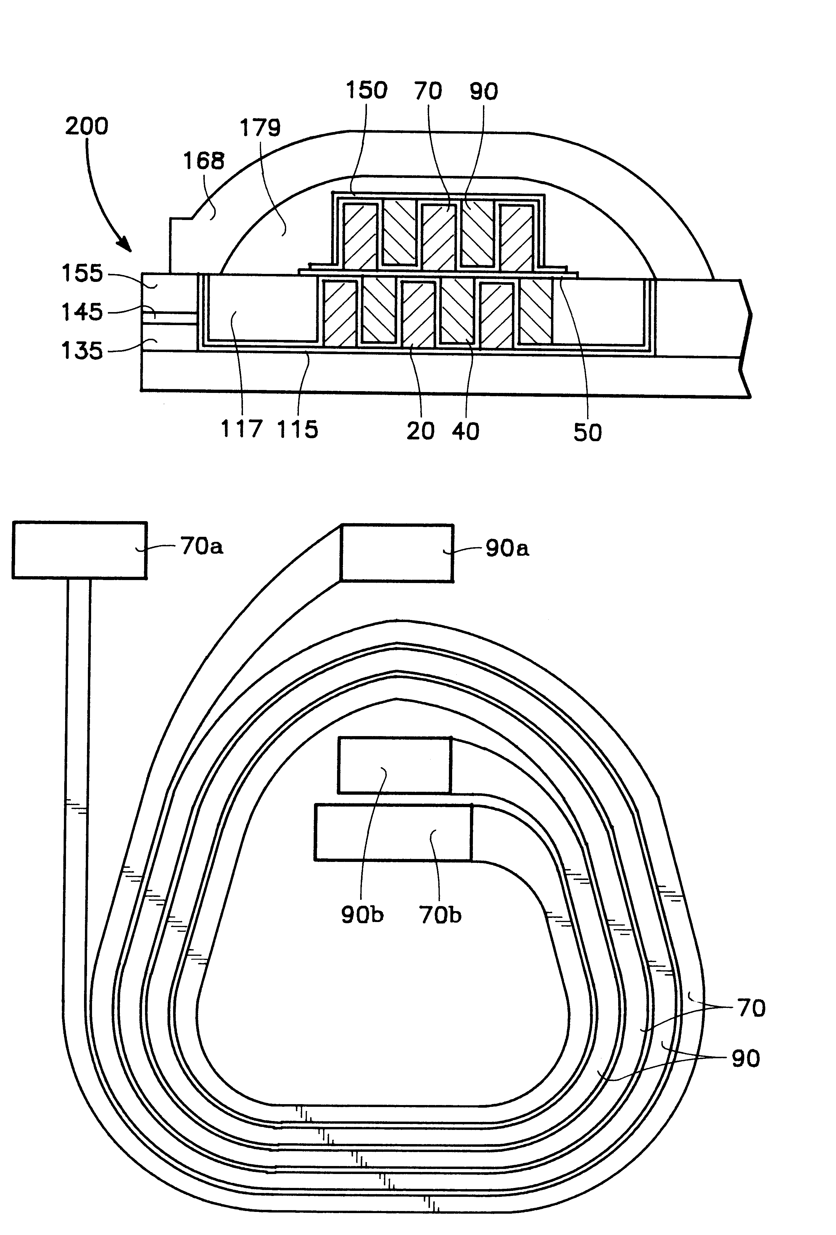
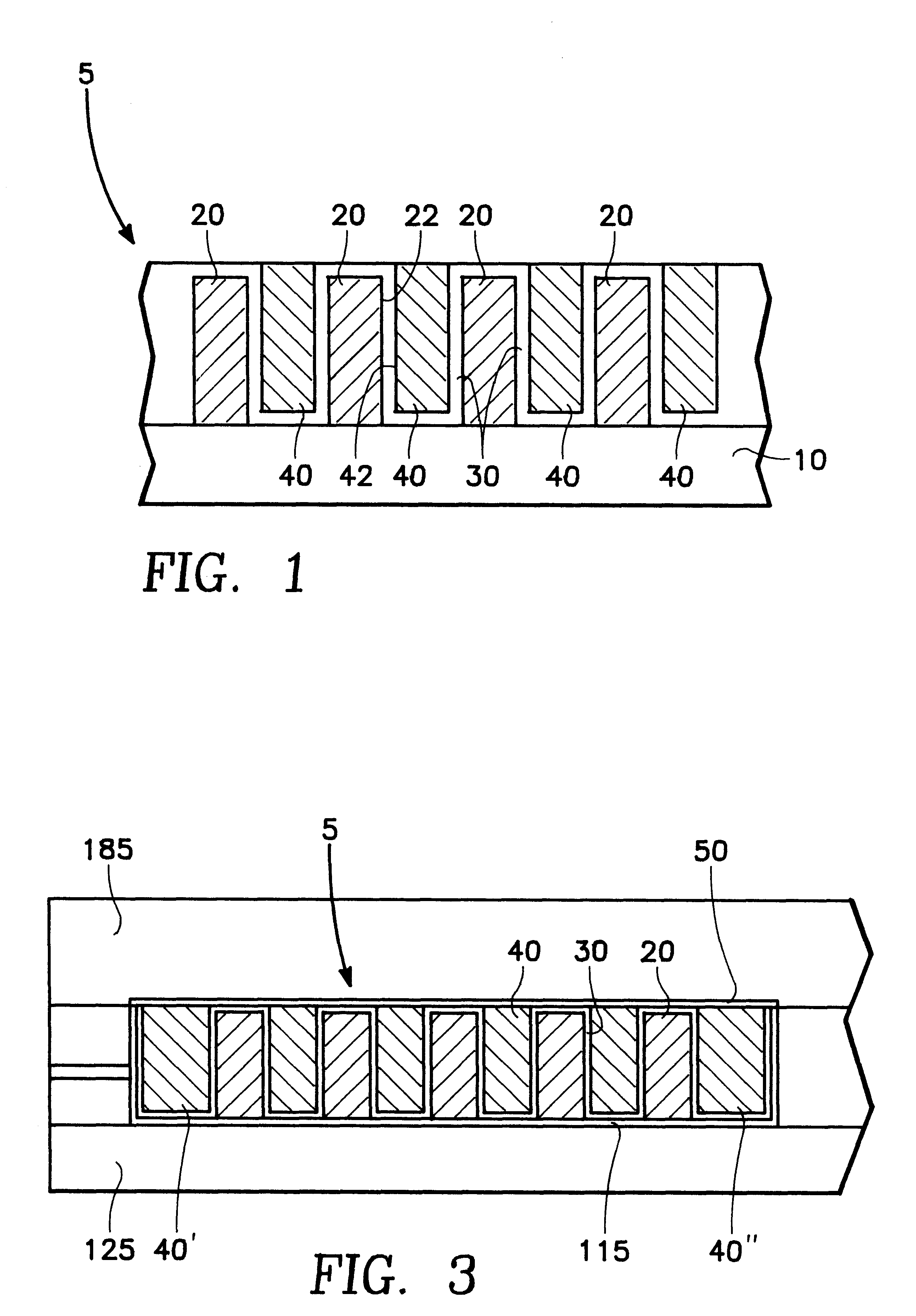
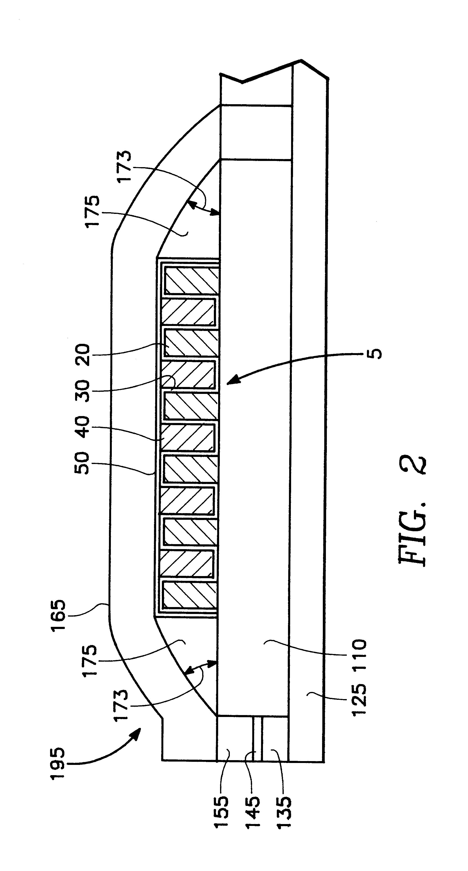
Interlaced Winding

FIG. 1

FIG. 1 shows a cross sectional view of a preferred embodiment of the coil structure of an interlaced conductor winding in accordance with the present invention. Turns of a first coil 20 are formed on an insulation layer 10 separated by a space. Turns of a second coil 40 are formed in the space between the turns of the first coil 20. As such, successive turns of the second coil 40 are disposed between successive turns of the first coil 20 to form an interlaced winding structure 5.

As will be discussed further below, the first coil 20 may be formed using a conventional resist pattern to define the structure of the first coil 20. The turns of the second coil 40 are formed between the turns of the first coil 20 after removal of the resist pattern. An insulation material 30, located between the sidewalls 22 & 42 of the first and second conductor coils 20 & 40, is deposited prior to formation of the second coil 40 to electrically isolate the turns of the winding 5.

S...


PUM


Abstract

The preferred embodiment of the present invention provides a write head having an interlaced conductor coil winding and method of fabrication. The interlaced winding of the present invention may have alternating turns of a first and a second coil. In the preferred embodiment, the side walls of successive coil turns are separated by an ultra thin inorganic insulation which defines the distance between successive turns of the first and second coil. In one method of fabrication, a conductive seed layer is deposited on a generally planar insulative surface, a resist mask is formed on the seed layer, and a conductive material deposited on the exposed seed layer to form the turns of the first coil. The masked portions of the seed layer are removed, after resist mask removal, to electrically isolate the turns of the first coil. The inorganic insulation may be formed in a layer conformal with the first coil. The second coil is formed between the turns of the first coil. A seed layer and mask may be used to facilitate second coil deposition. Etching, or planarization, may be used to electrically isolate the turns of the second coil. A capping layer may be formed over any exposed conductor material to insulate the winding from an upper pole structure or other overlying structure. Embodiments of the present invention may have multiple layers of conductor winding having some conventional, or all interlaced coil structure.

Description

1. Technical FieldThe present invention relates to the field of thin film write heads.2. Background ArtData is stored on magnetic media by writing on the magnetic media using a write head. Magnetic media can be formed in any number of ways, such as tape, floppy diskette, and hard disk. Writing involves storing a data bit by utilizing magnetic flux to set the magnetic moment of a particular area on the magnetic media. The state of the magnetic moment is later read, using a read head, to retrieve the stored information.Data density is determined by the amount of data stored on an area of magnetic media and depends on how much area must be allocated to each bit. Data on magnetic media is often stored in a line or track. Magnetic media often have multiple tracks. In the case of the disk, the tracks are nested annular rings. More bits per ring and more rings per disk increases data density. Data density, therefore, is determined not only by the bit length, but also by the width of the bi...

Claims


Application Information

Patent Timeline
IPC IPC(8): G11B5/31
CPCG11B5/313G11B5/3163
Inventor HONG, LIUBOBARR, RONALD A.
Owner WESTERN DIGITAL TECH INC
Why Eureka
Try Eureka