
Fault protection circuit for electronic balast of fluorescent lamp

An electronic ballast and protection circuit technology, applied in the field of vibration stop protection circuit, can solve the problems of cross range, inability to select the protection action critical value of the protection circuit, etc.

Inactive Publication Date: 2003-07-09
山拔克电子股份有限公司 +1
View PDF0 Cites 2 Cited by
  • Summary
  • Abstract
  • Description
  • Claims
  • Application Information

AI Technical Summary

Problems solved by technology

[0004] When the electronic ballast is working, when the lamp tube fails, the protection circuit of the general electronic ballast is to sample the current of the power circuit or the voltage on the lamp tube, and the protection circuit uses the current or voltage sampled during normal operation and failure. If the electronic ballast is used to drive multi-tube fluorescent lamps and only some of the lamps fail, the difference between the sampling signal at normal time and the sampling signal when some of the lamps are faulty is not large. If the lamps work at Under different circumstances, such as low voltage or low temperature, the sampling signal at normal time will cross the range of sampling signal when some lamp tubes are faulty, which makes it impossible to select the appropriate protection action threshold of the protection circuit

Method used


Image

  • Fault protection circuit for electronic balast of fluorescent lamp
  • Fault protection circuit for electronic balast of fluorescent lamp
  • Fault protection circuit for electronic balast of fluorescent lamp

Examples


Embodiment Construction

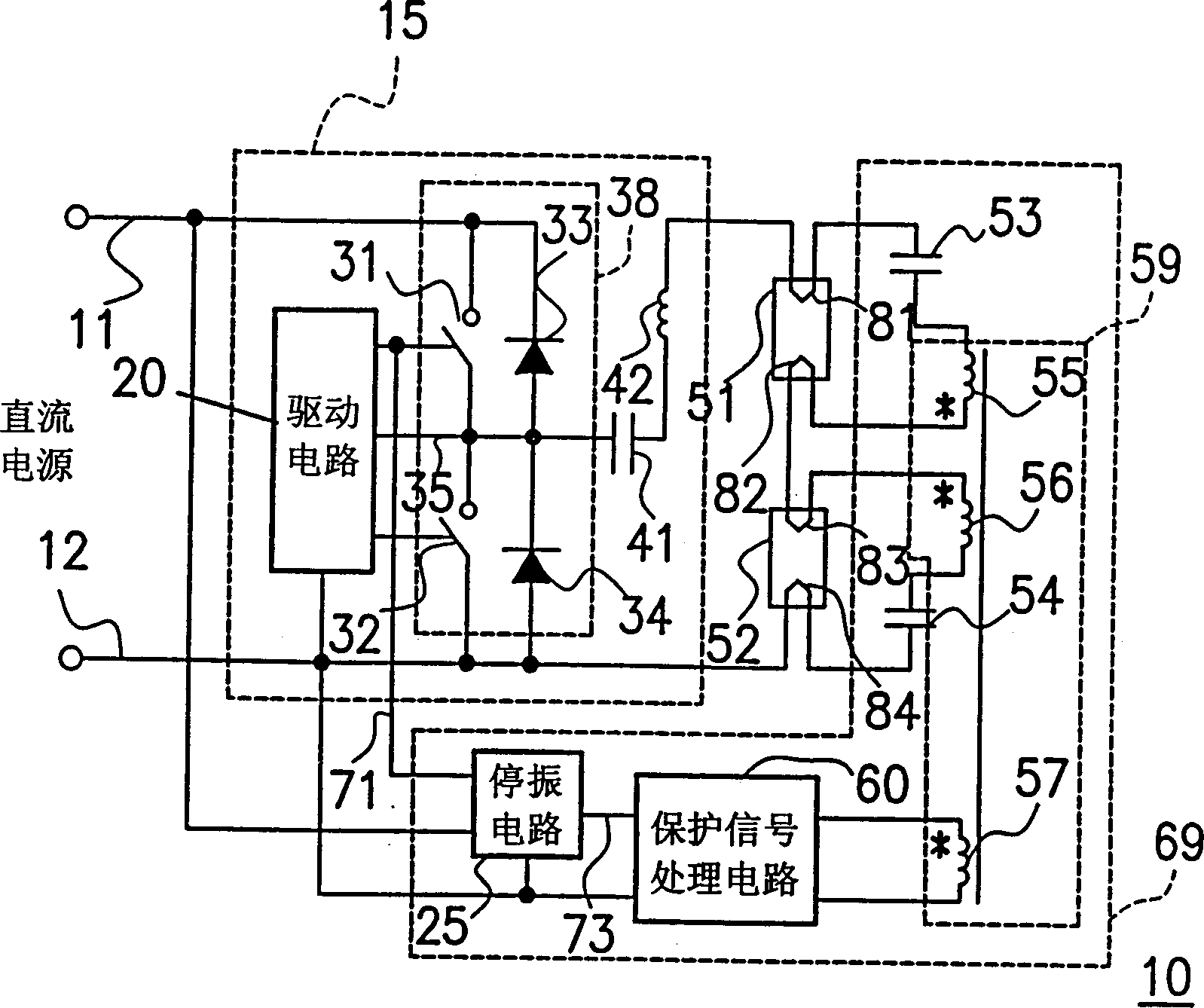
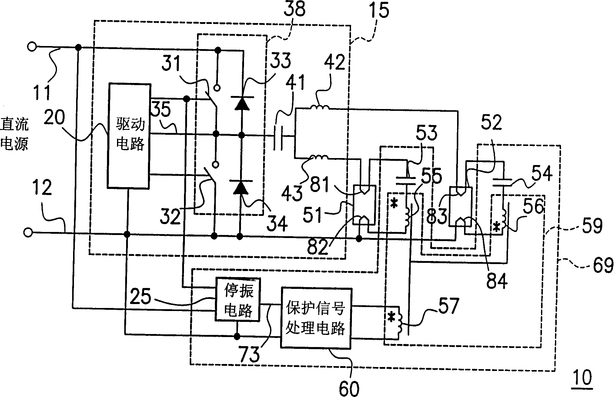
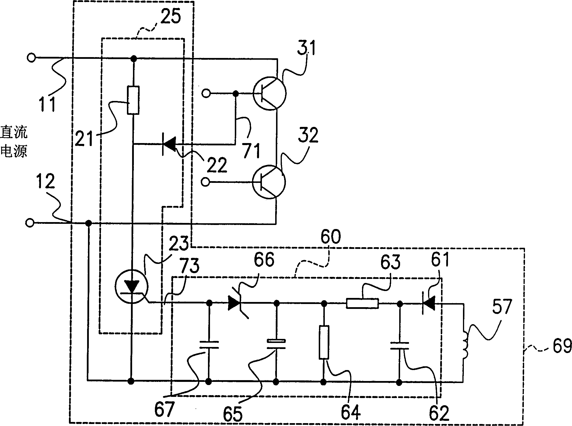
[0041] Electronic ballasts usually include circuits such as rectification, filtering, commutation and fault protection. The vibration stop protection circuit mentioned in this embodiment is to sample the power consumption of each lamp tube. When the sampled signal exceeds the set operating threshold , the vibration stop protection circuit stops the commutation circuit to achieve the purpose of protection, please refer to figure 1 , which is a circuit block diagram of an electronic ballast according to an embodiment of the present invention.

[0042] exist figure 1 Among them, the electronic ballast 10 has an inverter (Inverter) 15 and a vibration stop protection circuit 69, the inverter 15 is used to convert the DC power supply into a square wave power supply, and provide the square wave power supply to the lamp tubes 51, 52 (this The embodiment is based on the application of two lamp tubes as an example, but in fact it can be applied to more than two lamp tubes), and the vib...


PUM


Abstract

The protective circuit of oscillation stopping for electronic stabilizer in fluorescent lamp consists of several resonant capacitors, a sampling transformer, a processing circuit of protective signaland a oscillation-stopping circuit as the sampling transformer will separately sample of a normal sampling signal and a fault sampling signal which they two are made into a great deal of difference when lamp tube is in normal and in fault, the protective signal processing circuit will sent out a fault signal when it receives the fault sampling signal and the oscillation-stopping circuit will sendout a oscillation-stopping signal to inverter to make it stop working when the oscillation-stopping circuit receives the fault signal.

Description

technical field [0001] The invention relates to an electronic ballast of a fluorescent lamp, and in particular to a vibration stop protection circuit of the electronic ballast of a fluorescent lamp. Background technique [0002] Lighting equipment is already a part of people's lives, so the requirements for lighting equipment are getting higher and higher, such as reducing the flicker of the lamp tube, increasing the life of the lamp tube, improving the luminous efficiency of the lamp tube, and so on. In order to meet the above requirements, the electronic ballast (Electronic Ballast) was born. [0003] The electronic ballast can be used to drive single-tube fluorescent lamps or multi-tube fluorescent lamps. When the electronic ballast is used to drive multi-tube fluorescent lamps, the failure of some tubes must be considered. When multi-tube fluorescent lamps are working normally, the working characteristics of each lamp tube are relatively consistent, that is, the load is...

Claims


Application Information

Patent Timeline
IPC IPC(8): H05B41/298
CPCY02B20/183
Inventor 张康红赵建范邱义芳
Owner 山拔克电子股份有限公司
Learn More