Object plane adjustment method of optical projection system based on defocus depth analysis and its device

A technology of optical projection and depth of defocus, applied in optics, projection devices, optical components, etc., can solve problems such as not being able to adapt to mass production, and achieve the effects of high adjustment accuracy, simple operation, and fast adjustment speed

Inactive Publication Date: 2003-07-23
ZHEJIANG UNIV
View PDF0 Cites 11 Cited by
  • Summary
  • Abstract
  • Description
  • Claims
  • Application Information

AI Technical Summary

Problems solved by technology

This debugging method obviously cannot meet the needs of mass production

Method used


Image

  • Object plane adjustment method of optical projection system based on defocus depth analysis and its device
  • Object plane adjustment method of optical projection system based on defocus depth analysis and its device
  • Object plane adjustment method of optical projection system based on defocus depth analysis and its device

Examples


Embodiment Construction

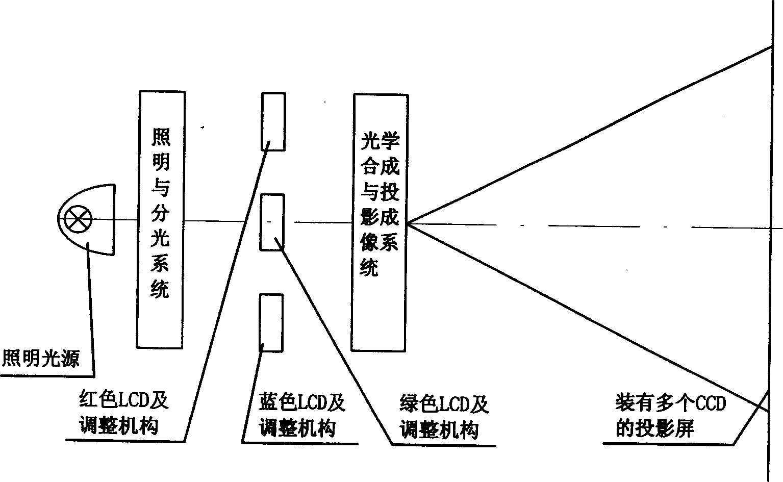
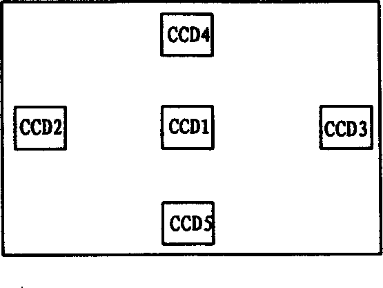
[0022] The object plane adjustment method of the optical projection system based on defocus depth analysis is characterized in that: multiple CCD image acquisition components are installed on the projection screen of the projection optical system to obtain images, and the object plane LCD of the optical projection system is obtained by analyzing the images. The defocus amount, horizontal tilt amount, vertical tilt amount, rotation amount and the relative position deviation of the three LCDs give the adjustment parameters.

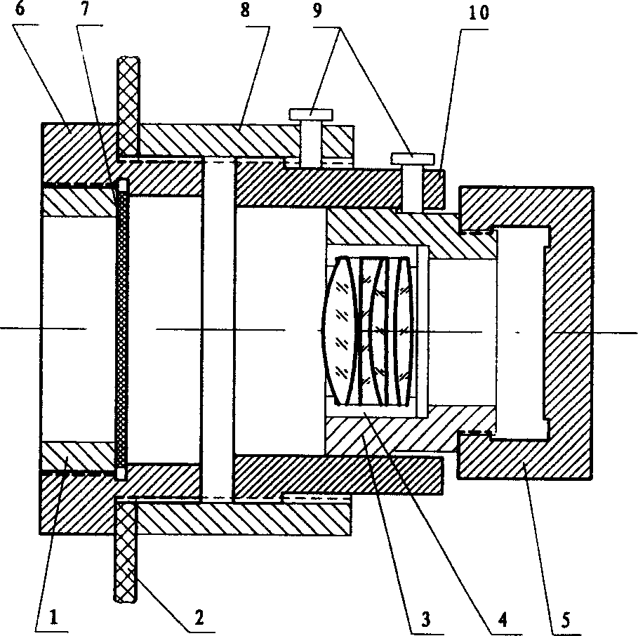
[0023] Said CCD image acquisition assembly is: frosted glass is installed at the position of the projection screen, an imaging lens is installed thereafter, a CCD device is installed at the rear of the lens, the frosted glass and the CCD surface are respectively conjugated with respect to the lens, so that the image on the projection screen diffuses through the frosted glass. After being shot, the image is imaged on the surface of the CCD through the lens. ...


PUM


Abstract

The invented defocus depth analysis is as follows. The multiple CCD image collection assemblies are installed on the projection screen of the projection optical system in order to obtain the images. The quantity of the defocus depth, the amount of inclination in horizontal direction and in vertical direction, the quantity of rotation of the LCD in the object plane of the optical projection systemas well as the relative position deviations of the three pieces of LCD are obtained. Then, the adjusting parameters are given out. The advantages of the invention are (1) High accuracy of the adjustment: the precision is assured by the system, not affected by the operators. (2) Fast adjustment speed; the settings with 18 degree of freedom are given at same time and suitable to the need of large scale of production. (3) Simple operation.

Description

technical field [0001] The invention relates to a method and a device for adjusting an object plane of an optical projection system based on defocus depth analysis. Background technique [0002] With the continuous advancement of various optical unit technologies, optical projection technology is gradually becoming mature, and mass production is being or has already been formed. The most typical ones are multimedia digital projectors, digital projection TVs, etc. The object plane of this type of projection system is generally LCD or other standard plates, films, etc. Because there are certain errors in the manufacturing process of optical parts and mechanical parts, and the entire optical system is very sensitive to errors, the installation error of LCD or target plate, and the manufacturing error of projection lens will make the projected image of the entire projection system not good. After adjustment, the projected image cannot be viewed at all. ...

Claims


Application Information

Patent Timeline
Patent Type & Authority Applications(China)
IPC IPC(8): G02B27/18G02B27/62G03B21/53G06T1/00
Inventor 冯华君徐之海李奇
Owner ZHEJIANG UNIV
Why Eureka
Try Eureka