
Melt sampler suitable especially for cinder floating over metal melt

A sampler and metal technology, applied in sampling, sampling devices, instruments, etc., can solve problems such as fragile and porous samples

Inactive Publication Date: 2003-07-30
HERAEUS ELECTRO NITE INT NV
View PDF1 Cites 1 Cited by
  • Summary
  • Abstract
  • Description
  • Claims
  • Application Information

AI Technical Summary

Problems solved by technology

Consequently, in many cases the removed samples become porous and brittle

Method used


Image

  • Melt sampler suitable especially for cinder floating over metal melt
  • Melt sampler suitable especially for cinder floating over metal melt
  • Melt sampler suitable especially for cinder floating over metal melt

Examples


Embodiment Construction

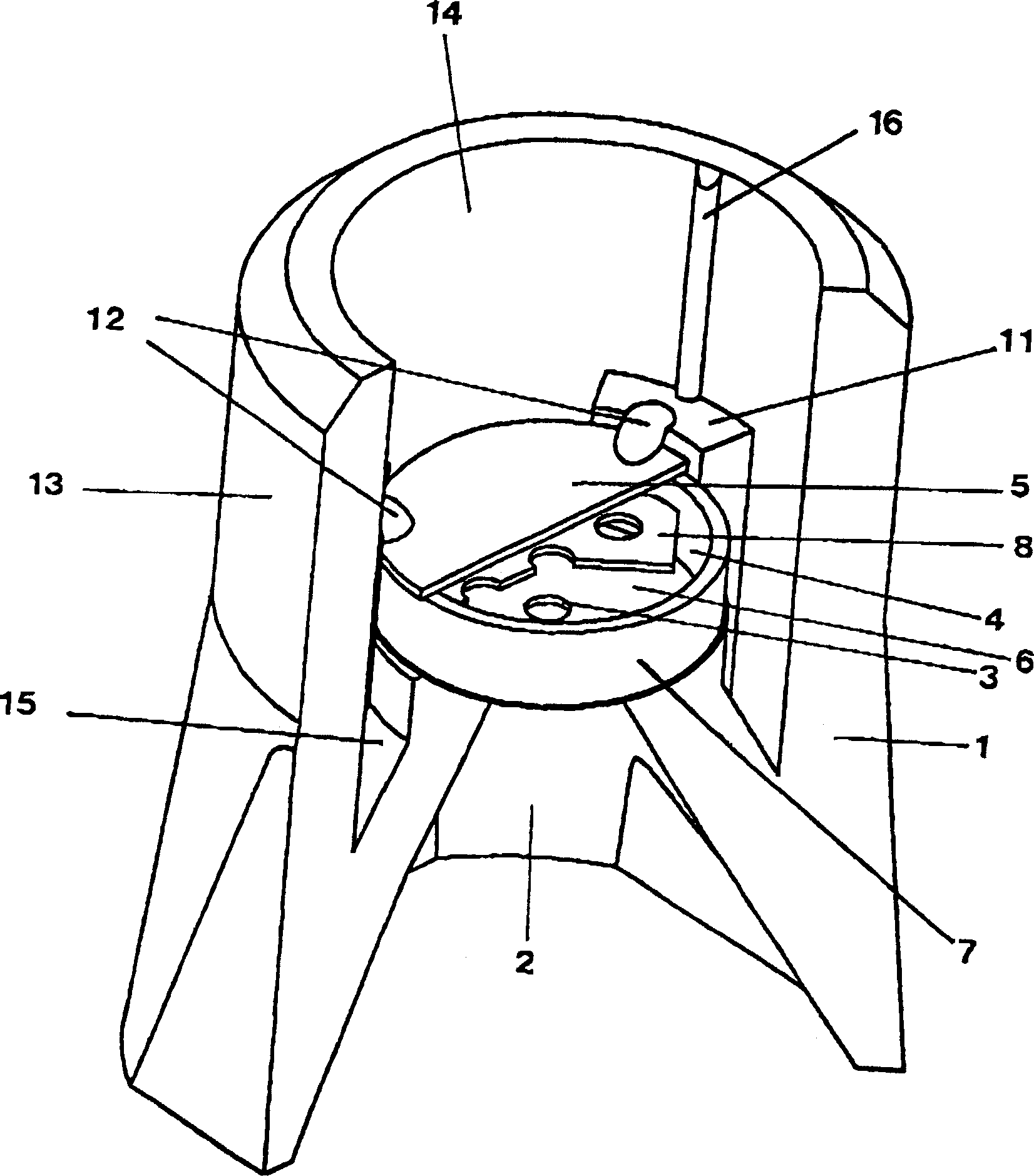
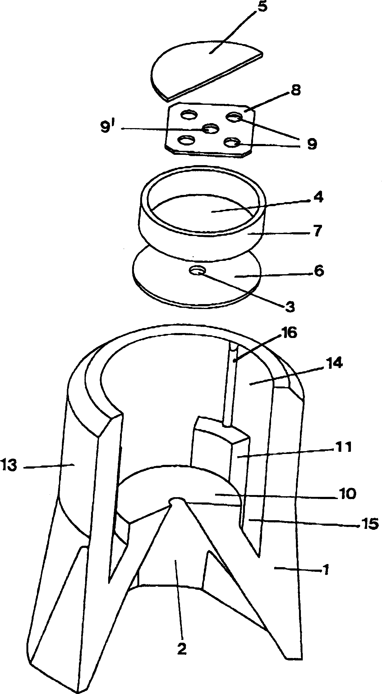
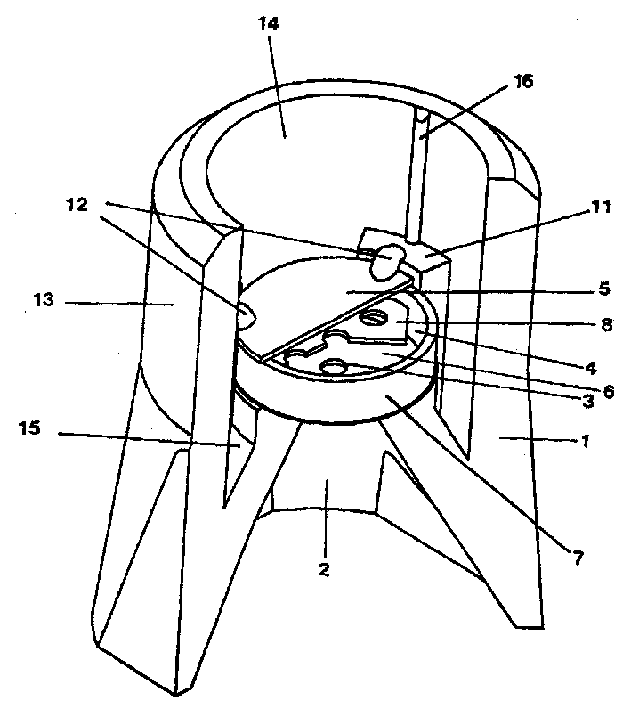
[0011] The housing 1 of the sampler is made of molding sand. It has a funnel-shaped inlet 2 which leads to a sampling chamber 4 via an inlet hole 3 . The sampling chamber 4 is a disk-shaped structure with a circular cross section. The sampling chamber walls 5 , 6 forming the base are also made of steel like the annular side wall 7 .

[0012] Inside the sampling chamber 4 , approximately midway between the two chamber walls 5 , 6 there is a partition plate 8 parallel to the chamber walls 5 , 6 . The steel partition plate 8 is provided with a plurality of holes 9, 9'. Around a central hole 9' with a diameter of about 8 mm, there are further four holes 9 with a diameter of about 5 mm, which are preferably evenly distributed around the circumference. It is also possible not to form a central hole or to arrange the spacer plates 8 in other arrangements. The partition plate 8 is fixed on the side wall 7 of the sampling chamber 4 .

[0013] The chamber wall 6 of the sampling cha...


PUM


Abstract

A sampler is provided for melts, in particular for slags lying on a molten metal, the sampler having a single- or multi-part body for arrangement in a support. The sampler has an inlet and a sample chamber with two opposing chamber walls, wherein an inlet opening is arranged in one chamber wall. In order to make possible homogeneous and stable samples, an intermediate plate with at least one through opening is arranged inside of the sample chamber spaced from the chamber walls.

Description

technical field [0001] The present invention relates to a melt sampler especially suitable for slag floating on the surface of a metal melt, the sampler comprising a one-piece or multi-part housing placed in a support, wherein an inlet is provided and a sampling chamber comprising two facing chamber walls, and an inlet hole is provided on one chamber wall. Background technique [0002] Such a sampler is known from DE 100 49 253 A1. They are especially suitable as slag samplers. Such slag generally contains gas bubbles. As a result, the removed samples became porous and brittle in many cases. Contents of the invention [0003] The object of the invention on which the present invention is based is to improve the known sampler and to enable a more stable sampling. [0004] According to the present invention, the object of the invention is achieved by means of the following technical features: in the sampling chamber, a partition plate is provided at a certain distance fro...

Claims


Application Information

Patent Timeline
Patent Type & Authority Applications(China)
IPC IPC(8): G01N1/04G01N1/12
CPCG01N1/125
Inventor 约翰·克内费尔斯吉多·古斯塔夫·安东·卡帕弗兰克·明内奥
Owner HERAEUS ELECTRO NITE INT NV
Learn More