Cryogenic refrigerator and control method therefor

A technology of refrigeration device and control method, which is applied in refrigerators, refrigeration components, cold treatment separation, etc., can solve the problems of load application, driving system and other adverse effects, and high pressure resistance of pressure vessels.

Inactive Publication Date: 2012-07-18
IHI CORP
View PDF1 Cites 0 Cited by
  • Summary
  • Abstract
  • Description
  • Claims
  • Application Information

AI Technical Summary

Problems solved by technology

In this case, if it is released to the outside, the loss of expensive working gas will be large, and if it is pumped into the pressure vessel, the pressure resistance of the pressure vessel will become too high
[0015] Furthermore, in the case of stopping the entire refrigerator as it is without using a pressure vessel, it is necessary to increase the compressive strength of the entire refrigerator in advance.
Also, in this case, there is a problem of an excessive load on the compressor at start-up
[0016] In addition, if the refrigerator is suddenly stopped due to emergency stop, etc., the working gas on the high-pressure side will flow back through the compressor, and the compressor will rotate in reverse, which may have a bad influence on the drive system, etc.

Method used


Image

  • Cryogenic refrigerator and control method therefor
  • Cryogenic refrigerator and control method therefor
  • Cryogenic refrigerator and control method therefor

Examples


Embodiment

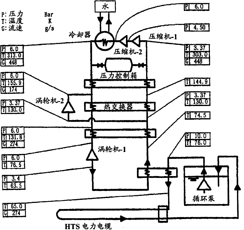
[0081] Figure 5It is a figure which shows 2nd Embodiment of the cryogenic freezer concerning this invention. This example is an embodiment in which the outlet temperature of the cryogenic part is 65K and the cooling capacity is 3kW. P, T, H, and G in the figure represent pressure (bar), temperature (K), and mass flow rate (g / s), respectively.

[0082] In this example, the room temperature compressor 14 is composed of a first-stage compressor 14A that compresses from a specified low pressure (5.57 bar) to a first intermediate pressure (8.03 bar) between the low pressure and high pressure, and compresses from the first intermediate pressure to a high pressure. (11.0bar) second-stage compressor 14B constitutes. Water-cooled gas coolers 15 are provided on the downstream side (high pressure side) of the first-stage compressor 14A and the second-stage compressor 14B, respectively.

[0083] In addition, the expander 18 consists of a first expander 18A that expands from a high pres...


PUM


Abstract

A cryogenic refrigerator (10) which creates a cryogenic temperature condition by compressing and expanding working gas in a closed loop (11). The cryogenic refrigerator comprises a bypass line (22) allowing a high-pressure portion and a low-pressure portion to communicate with each other, a gas storage tank (24) located midway in the bypass line and including pressure regulation valves (23a, 23b)on the high-pressure side and the low-pressure side respectively, and a pressure control unit (26) controlling the pressure regulation valves. The pressure control unit (26) controls the pressure regulation valves (23a, 23b) such that the pressure in the gas storage tank (24) is equal to that in the closed loop at room temperature and in a stopped state and is between those in the high-pressure portion and the low-pressure portion and close to that in the low-pressure portion in an operating state.

Description

technical field [0001] The present invention relates to an ultra-low temperature refrigeration device capable of cooling an object to be cooled to an ultra-low temperature and a control method thereof. Background technique [0002] In order to perform high temperature superconducting (HTS) equipment (such as superconducting power transmission cables, superconducting transformers, superconducting motors, superconducting coils for superconducting power storage, large accelerators, nuclear fusion test equipment, MHD power generation, superconducting coils, etc.) Cool, using a very low temperature freezer (eg Brayton cycle freezer or Erickson cycle freezer). [0003] For example, in the case of cooling high-temperature superconducting equipment, the lowest temperature range is 65K, 40K, 30K, 20K, etc. depending on the type and application of the superconducting wire. In addition, at each temperature, the refrigeration output is about 1 to 10 kW, and the refrigerant gas uses hel...

Claims


Application Information

Patent Timeline
Patent Type & Authority Patents(China)
IPC IPC(8): F25B9/06F25B9/00F25J1/00
CPCF25J2270/16F25B2600/2519F25B9/14F25J1/005F25B2309/1401F25J1/0065F25B45/00F25B9/06F25J2270/912F25B2500/27F25J2245/02F25J1/0248F25B2400/16F25J1/0062F25J1/0276F25J1/0288
Inventor 佐治脩好高桥俊雄吉永诚一郎胁阪裕寿
Owner IHI CORP
Why Eureka
Try Eureka