Driving device and method for display device

A technology for a display device and a driving device, applied to static indicators, instruments, etc., can solve the problems of rising cost, inability to switch the power supply mode, inability to switch the master mode and slave mode, etc., to achieve the effect of reducing costs

Inactive Publication Date: 2003-08-06
SHARP KK
View PDF1 Cites 5 Cited by
  • Summary
  • Abstract
  • Description
  • Claims
  • Application Information

AI Technical Summary

Problems solved by technology

[0028] In addition, in the above-mentioned conventional structure, if the liquid crystal driver (LSI) is packaged once, the power supply method (current supply capability) cannot be switched.
That is, it is not possible to switch between master mode and slave mode in the LCD driver
Therefore, when the capacity of the power supply is insufficient due to the display state, the voltage supply method cannot be switched to the voltage supply method with the required capacity on the display.
As a result, it is often necessary to set the power supply assuming the maximum power consumption, which leads to an increase in cost

Method used


Image

  • Driving device and method for display device
  • Driving device and method for display device
  • Driving device and method for display device

Examples


Embodiment Construction

[0044] based on the following Figure 1 to Figure 6 An example of the present invention will be described.

[0045] In this embodiment, the driver device for a display device according to the present invention is applied to a liquid crystal display device, and a case of a double scanning method in a load driving method using an STN liquid crystal panel is shown.

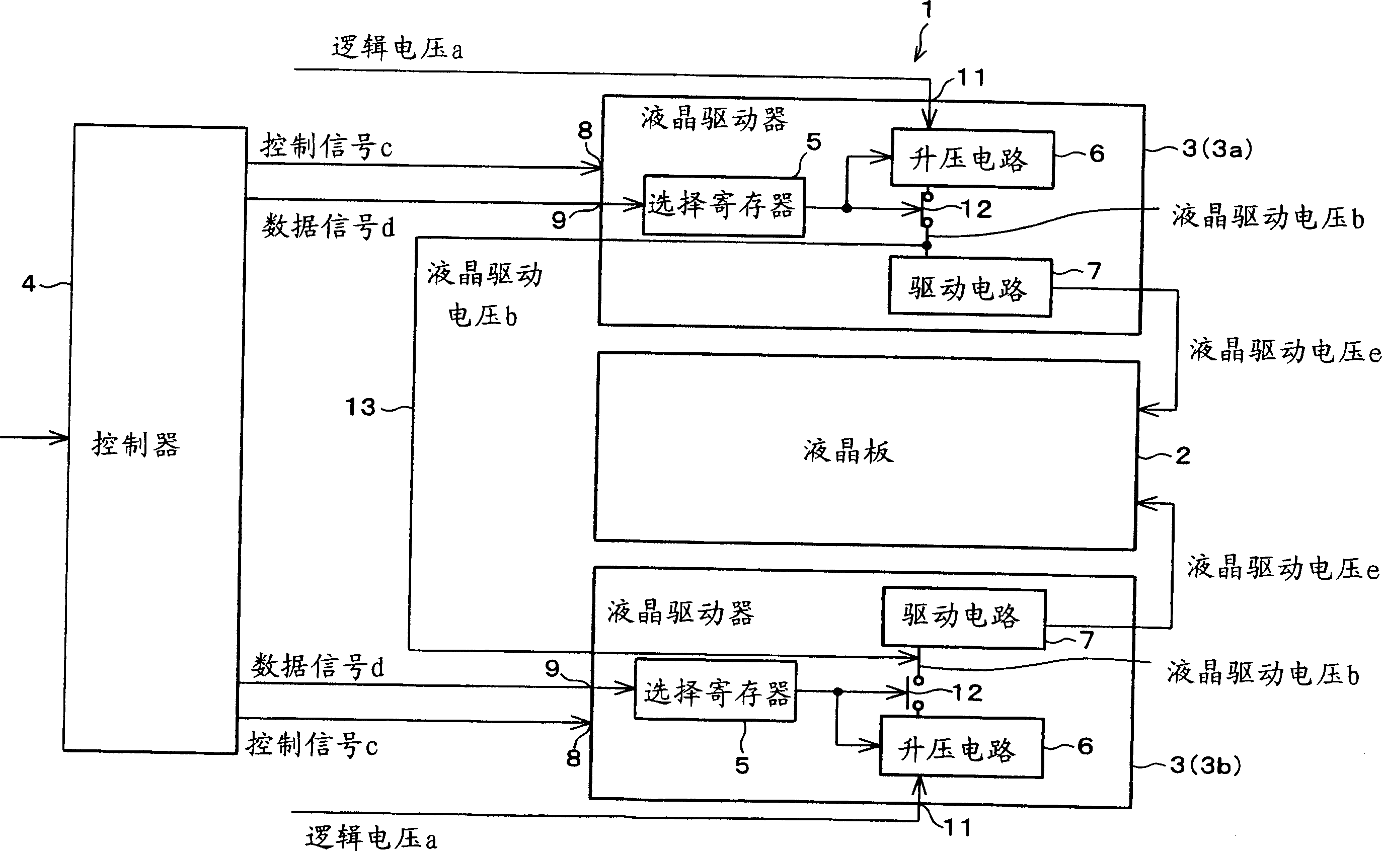
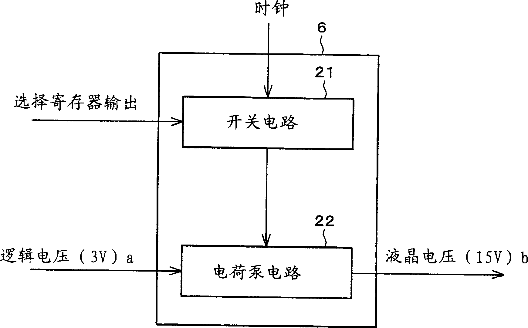
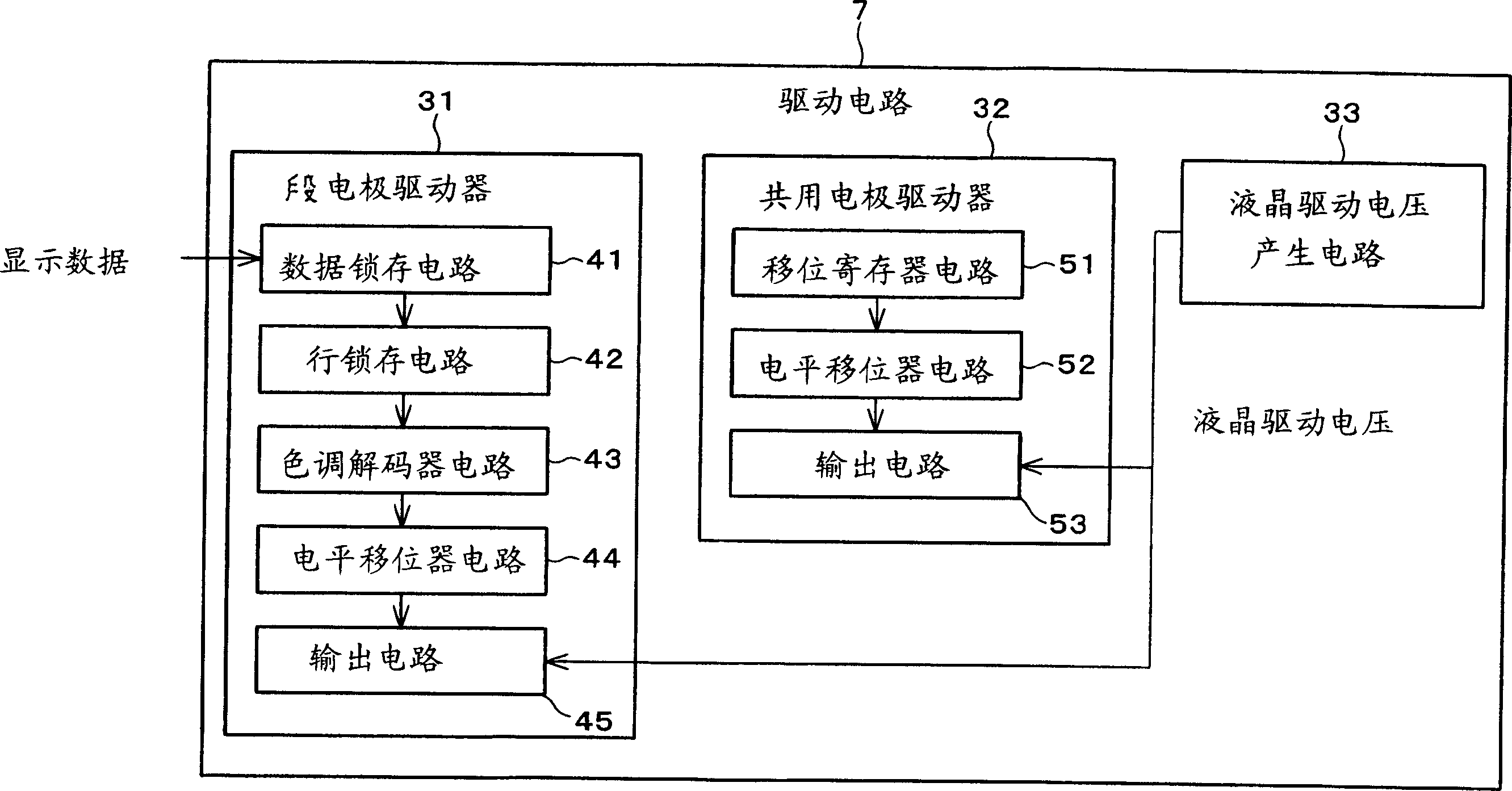
[0046] figure 1 The basic structure of the drive device 1 for a display device is shown. As shown in the figure, a display device driving device 1 drives a liquid crystal panel 2 as a display device, and includes a plurality of liquid crystal drivers (drive voltage output means) 3 and a controller 4 . In this embodiment, two liquid crystal drivers 3 are provided. Each liquid crystal driver 3 is provided with a selection register (mode storage section) 5 , a voltage boosting circuit 6 and a driving circuit 7 .

[0047] In the liquid crystal driver 3 , the control signal c is input from the controller 4 to the con...


PUM


Abstract

The display device drive unit includes a liquid crystal driver that generates a liquid crystal driving voltage for display device driving, and can operate in a master mode for outputting the foregoing voltage and in a slave mode for driving the display device in accordance with the liquid crystal driving voltage that has been inputted from the outside. The display device drive unit further includes a selection register for storing mode information that indicates whether the liquid crystal drivers is set to be in the master mode or the slave mode, and the liquid crystal driver outputs the liquid crystal voltage when the mode information indicative of the master mode is stored, and stops outputting the foregoing voltage when the mode information indicative of the slave mode is stored. Thus, it is not necessary to provide a setting terminal for switching between the master mode and the slave mode, and it is also possible to switch between both the modes after the drive unit has been packaged in the display device.

Description

technical field [0001] The present invention relates to, for example, a display device drive device suitable for a liquid crystal panel and a display device drive method. Background technique [0002] For example, a liquid crystal driver for driving a liquid crystal panel is provided in a liquid crystal display device. The liquid crystal driver forms a liquid crystal drive output for driving a liquid crystal panel from a liquid crystal drive voltage. In this liquid crystal driver, in order to obtain the above-mentioned liquid crystal driving voltage, the following techniques have conventionally been mainly used in accordance with the purpose of use of the liquid crystal panel. [0003] 1. A liquid crystal driving voltage is supplied to a plurality of liquid crystal drivers from an external power supply provided for the liquid crystal drivers. [0004] 2. From the logic drive power supply, the logic voltage and common voltage are supplied to the liquid crystal panel, and th...

Claims


Application Information

Patent Timeline
Patent Type & Authority Applications(China)
IPC IPC(8): G02F1/133G09G3/20G09G3/36
CPCG09G3/3611G09G3/20G09G2330/02G09G3/3696G09G3/36
Inventor 胜谷昌史
Owner SHARP KK
Why Eureka
Try Eureka