Projection device
A projection device and projection technology, applied in projection devices, optics, instruments, etc., can solve problems such as interference of display data, influence on display work, interference of data display effects, etc., to achieve the best creativity and practicability, best display effect, and display work Convenience and Efficiency
- Summary
- Abstract
- Description
- Claims
- Application Information
AI Technical Summary
Problems solved by technology
Method used
Image
Examples
no. 1 example
[0057] The first embodiment ( Figures 2A to 2B )
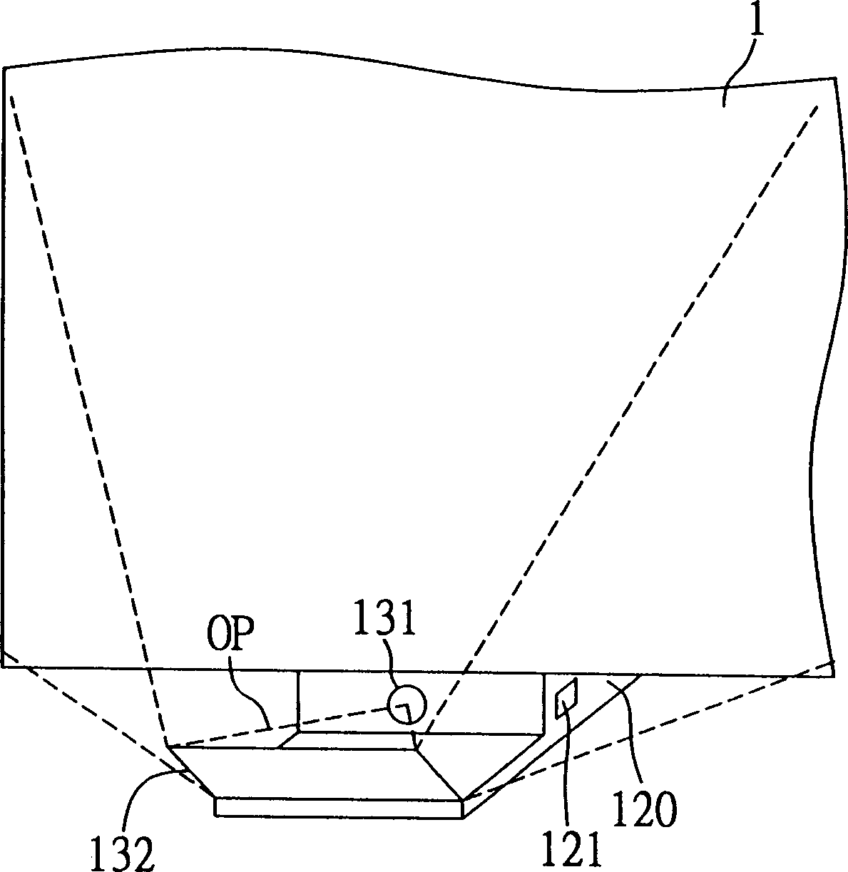
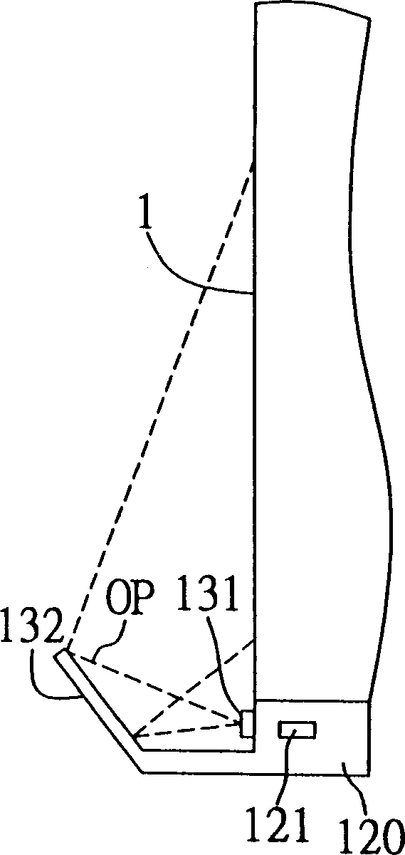
[0058] Figure 2A and 2B It is a structural diagram, which respectively shows the structural form of the first embodiment of the projection device of the present invention in front view and side view.
[0059] Please also see Figure 2A and 2B , the projection device of the present invention can be installed on the bottom side of a display area 1 for displaying an optical image OP, and its basic components include at least one projection processing module 120 . Here, it should be noted that the projection device of the present invention can also be installed on the left side, right side, or top side of the display area 1, that is, the projection device of the present invention can be determined according to the desired embodiment. The installation position of the device, and the location of the display area 1 can be any place where the projected image can be displayed, such as a wall, a general whiteboard, an electronic ...
no. 2 example
[0063] The second embodiment ( Figures 3A to 3B )
[0064] Figure 3A and 3B It is a structural diagram, which respectively shows the structural form of the second embodiment of the projection device of the present invention in front view and side view.
[0065] Please also see Figure 3A and 3B , the projection device of the present invention can also be used to match an electronic whiteboard 100 , and its basic components include at least: (a) a computer platform 110 ; and (b) a projection processing module 120 .
[0066] The electronic whiteboard 100 is provided with a specific connection interface 101 , such as a standard wired RS-232 interface, for connecting the electronic whiteboard 100 to the computer platform 110 . A feature of the present invention is that the connection between the electronic whiteboard 100 and the computer platform 110 adopts a fixed built-in circuit, so users can use the projection device of the present invention without using disturbing ext...
no. 3 example
[0070] The third embodiment ( Figures 4A to 4B )
[0071] Figure 4A and 4B It is a structural diagram, which respectively shows the structural form of the third embodiment of the projection device of the present invention in front view and side view.
[0072] Please also see Figure 4A and 4B , the projection device of the present invention is used to match to an electronic whiteboard 200, and its basic components include at least: (a) a computer platform 210; and (b) a projection processing module 220.
[0073] The electronic whiteboard 200 is the same as the first embodiment, and is also provided with a specific connection interface 201 for connecting the electronic whiteboard 200 to the computer platform 210 . The computer platform 210 is also the same as the first embodiment, wherein some standard data storage devices 211 (such as DVD ROM optical drive, hard disk drive, floppy disk drive, etc.) and communication interfaces 212 (such as USB, RS-232, PS / 2 etc.). Si...
PUM
 Abstract
Description
Claims
Application Information
 - R&D
- Intellectual Property
- Life Sciences
- Materials
- Tech Scout
- Unparalleled Data Quality
- Higher Quality Content
- 60% Fewer Hallucinations
Browse by: Latest US Patents, China's latest patents, Technical Efficacy Thesaurus, Application Domain, Technology Topic, Popular Technical Reports.
© 2025 PatSnap. All rights reserved.Legal|Privacy policy|Modern Slavery Act Transparency Statement|Sitemap|About US| Contact US: help@patsnap.com


