Band device for a wheel rim

A technology for pads and rims, applied in the field of pads for rims, to achieve the effect of reducing the total weight

Inactive Publication Date: 2003-08-20
蒂龙爆胎保护有限公司
View PDF0 Cites 45 Cited by
  • Summary
  • Abstract
  • Description
  • Claims
  • Application Information

AI Technical Summary

Problems solved by technology

The reason for this is that once the beadlock is installed in the tire, it cannot be adjusted

Method used


Image

  • Band device for a wheel rim
  • Band device for a wheel rim
  • Band device for a wheel rim

Examples


Embodiment Construction

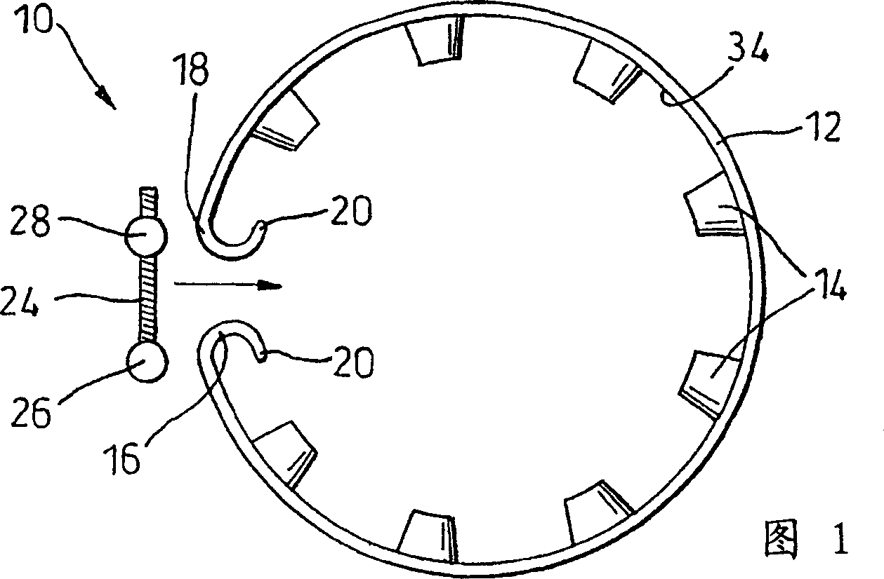
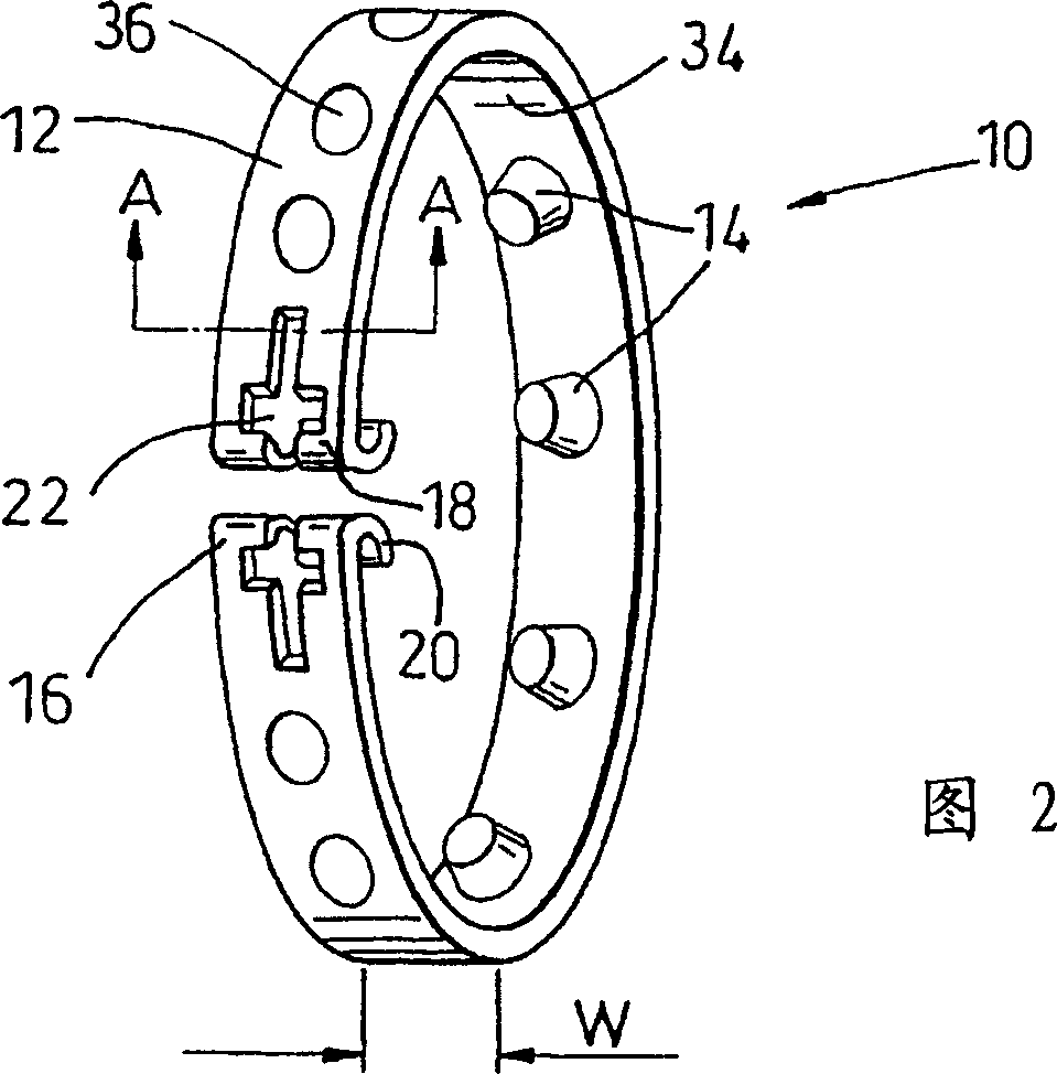
[0079] 1 and 2 show a flat tire travel assembly 10 according to an embodiment of the present invention.

[0080] This flat tire running assembly 10 comprises a support cushion belt 12 and a plurality of butt feet 14, wherein the support cushion belt is made of less ductile materials such as steel, and the support feet are made of tougher load-bearing non-woven fabrics. Metal materials such as high-density polyethylene or nylon reinforced with glass fibers.

[0081] At a certain point on its circumference, the back-up mat strip 12 is split so that two opposing end portions 16,18 are formed on the back-up mat strip 12 . Each of the opposing end portions 16, 18 has a bent lip portion 20 which is bent inwardly towards the center of the support pad strip 12.

[0082] In addition to the bent lip portion 20, each opposite end 16, 18 is also provided with a cross-shaped hole 22 (see FIG. Corresponding holes 22 pass through to operatively connect the two opposite ends 16, 18 to each ...


PUM


Abstract

An assembly ( 10 ) for location around a wheel rim ( 32 ) includes an annular support band ( 12 ) being formed of a relatively inextensible material. The support band ( 12 ) is split at at least one circumferential location to define a pair of opposed ends ( 16, 18 ). Adjustment bolt ( 24 ) is operably connected to the opposed ends ( 16, 18 ) for enabling adjustment of the diameter of the support band ( 12 ), and feet ( 14 ) depend from the radially inner face ( 34 ) of the support band ( 12 ). The feet ( 14 ) are formed from a relatively non-compressible material and, in use, are seated upon the wheel rim ( 32 ) to maintain the support band ( 12 ) in a spaced apart relationship with the wheel rim ( 32 ). The assembly may be adapted for use as a runflat assembly or as a beadlock assembly.

Description

technical field [0001] The invention relates to a component installed around the rim of a wheel, which can be used as a flat tire running component of the wheel or as a bead lock ring component according to the specific structure of the rim. Background technique [0002] A wheel usually includes a pneumatic tire supported on a rim. The rim generally includes a pair of rims separated in the axial direction, and in operation, the two beads of the tire are pressed against the pair of rims. [0003] Between the two rims of the integral wheel, the rim generally has a wheel groove into which the bead of the tire sinks when the tire is installed and removed, so that the bead can pass over the rim of the rim. [0004] In the case of a punctured tire, when the wheel turns (this article will refer to this situation as "running flat"), if the tire is severely deflated, the tire will move from Fall off the rim. If this happens, steering control of the wheels is lost and the vehicle l...

Claims


Application Information

Patent Timeline
Patent Type & Authority Applications(China)
IPC IPC(8): B60B21/12B60C15/028B60C17/04
CPCB60C17/041B60B21/12B60C15/028B60C17/04B60B21/125B60B21/04
Inventor 理查德·D·卢斯特
Owner 蒂龙爆胎保护有限公司
Why Eureka
Try Eureka