Bearing with wireless self-powered sensor unit

A sensor and sensor device technology, which is applied in the direction of rotating bearings, bearings, roller bearings, etc., can solve the problems of inability to monitor temperature rise and fewer sensors.

Inactive Publication Date: 2003-08-20
THE TIMKEN CO
View PDF0 Cites 32 Cited by
  • Summary
  • Abstract
  • Description
  • Claims
  • Application Information

AI Technical Summary

Problems solved by technology

For example, railroads have trackside infrared sensors that monitor the journal bearings of passing trains, but these sensors are located in relatively few locations, often many miles apart, and will not be able to detect the temperature rise

Method used


Image

  • Bearing with wireless self-powered sensor unit
  • Bearing with wireless self-powered sensor unit
  • Bearing with wireless self-powered sensor unit

Examples


Embodiment Construction

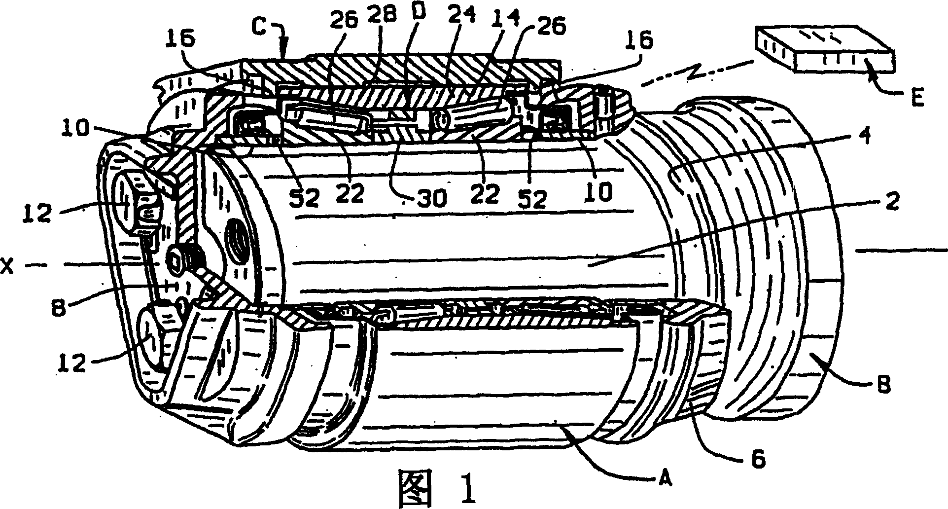
[0015] Now looking at the drawings, the double-row tapered roller bearing A can make the railcar axle B rotate in the joint C with minimal friction, and then install it on the railcar bogie (Figure 1). Bearing A includes an internal sensor device or unit D, which generates a signal when the axle B rotates about the axis X of the bearing A. In a preferred embodiment, the sensor unit D is self-powered and wireless, and is set within the limited range of bearing A. It generates a signal indicating the condition of bearing A and its operation, which will indicate the condition and operating characteristics of the bearing. The information is sent to the remote receiver E by radio signal transmission. In this way, for example, the angular velocity of the bearing A and the shaft B can be measured far away from the bearing A, the operating temperature of the bearing A, and the severe vibration in the bearing A can also be measured. But the bearing A and the sensor unit D are kept separate...


PUM


Abstract

A tapered roller bearing having its rollers arranged in two rows within an outer race and around an inner race contains a sensing device that radiates signals which reflect conditions within the bearing. In one embodiment, the outer race is unitary and the sensing device is wireless and self-powered and includes a mounting ring that is fitted to the outer race between the raceways along which the rollers roll. The ring has embedded within it several sensors for monitoring bearing conditions such as temperature and vibrations. The ring also contains a radio transmitter, a microprocessor to which the sensors are connected, and a power supply for producing the electrical energy required to operate the processor and the transmitter. The electric power is generated by means of electromechanical energy conversion using permanent magnets, armature winding and a target wheel that is captured between and rotates with the two cones. The transmitter converts conditions registered by the sensors and processed by the processor into radio signals which are received externally from the bearing. In another embodiment the unitary outer race has a groove which opens inwardly between the two rows of rollers, and the sensors, radio transmitter, processor, and power supply are located within the groove. In other embodiments the inner race is unitary and the sensors, radio transmitter, processor and power supply are carried by the inner race.

Description

Technical field [0001] The present invention generally relates to an anti-friction bearing, and more particularly to an anti-friction bearing, which generates a signal reflecting the relevant state of the bearing under the action of the electric power from the inside of the bearing. Background technique [0002] A typical anti-friction bearing has inner and outer races and rolling elements. The inner and outer races are arranged with opposite raceways, and the rolling elements are positioned between the inner and outer races. When the bearing is working, the rolling elements roll along The track rolls, thereby minimizing wear. The bearing contains lubricant, and the end of the bearing is sealed by the bearing to prevent dirt from entering the bearing and naturally keep the lubricant inside the bearing. Bearings usually fail due to lack of lubricant or defects in one of the bearing raceways or rolling elements. However, the raceways and rolling elements are completely covered and ...

Claims


Application Information

Patent Timeline
Patent Type & Authority Applications(China)
IPC IPC(8): F16C41/00B61K9/04F16C19/38F16C19/52G01P3/44
CPCF16C19/386F16C19/522F16C19/527F16C41/004B61K9/04F16C19/525G01P3/446F16C19/385F16C41/008B21B99/00
Inventor M·弗兰奇K·M·伊夫特哈如丁D·R·利珀R·P·萨米W-R·黄
Owner THE TIMKEN CO
Why Eureka
Try Eureka