Liquid-crystal displaying apparatus

A liquid crystal display device, liquid crystal technology, applied in identification devices, instruments, nonlinear optics, etc., can solve the problem of not being able to fully improve the display quality

Inactive Publication Date: 2003-08-27
SHARP KK
View PDF1 Cites 9 Cited by
  • Summary
  • Abstract
  • Description
  • Claims
  • Application Information

AI Technical Summary

Problems solved by technology

[0008] However, the present inventors have found that display quality cannot be sufficiently improved merely by providing an electrode structure as disclosed in this patent application

Method used


Image

  • Liquid-crystal displaying apparatus
  • Liquid-crystal displaying apparatus
  • Liquid-crystal displaying apparatus

Examples


Embodiment Construction

[0101] Embodiments of the present invention will now be described with reference to the drawings.

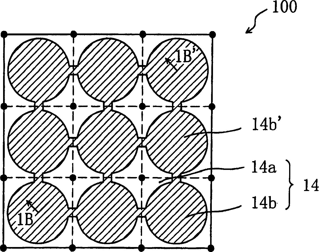
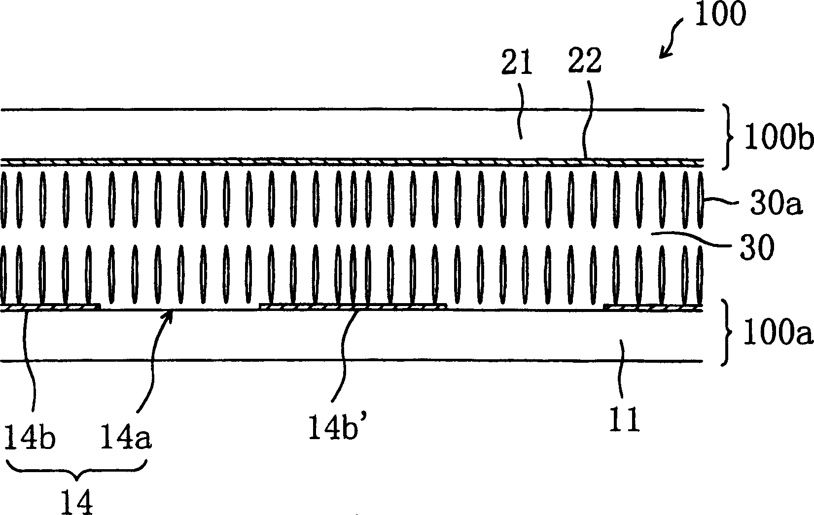
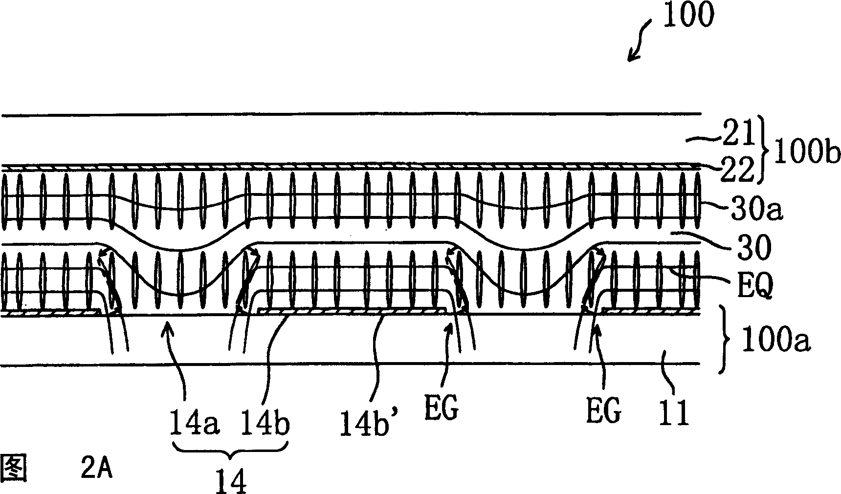
[0102] First, the electrode structure of the liquid crystal display device of the present invention and its function will be described. Hereinafter, preferred embodiments of the present invention will be described with respect to an active matrix type liquid crystal display device using thin film transistors (TFTs). Also, although the preferred embodiment of the present invention will be described in relation to a transmissive liquid crystal display device, alternatively, the present invention may use a reflective liquid crystal display device or a combined transmissive / reflective liquid crystal display device.

[0103] Note that in this specification, an area of ​​the liquid crystal display device corresponding to a "pixel" will be referred to as a "pixel area", which is a minimum unit of display. In a color liquid crystal display device, R, G, and B "pixels" correspond to one...


PUM


Abstract

A first substrate includes, on one side thereof that is closer to a liquid crystal layer, a picture element electrode provided for each picture element region, a switching element, and a bus line. A second substrate includes a counter electrode opposing the picture element electrode. The picture element electrode includes a plurality of openings and a solid portion that includes a plurality of unit solid portions. In each picture element region, the liquid crystal layer takes a vertical alignment in the absence of an applied voltage, and forms a plurality of liquid crystal domains, each of which takes a radially-inclined orientation, in the plurality of openings and the solid portion by inclined electric fields produced at respective edge portions of the plurality of openings of the picture element electrode in response to an applied voltage. In each picture element region, at least one of the plurality of openings of the picture element electrode that is located along the bus line and located between two adjacent ones of the plurality of unit solid portions is superposed on the bus line.

Description

technical field [0001] The invention relates to a liquid crystal display device, in particular to a liquid crystal display device with wide viewing angle characteristics and capable of producing high-quality display. Background technique [0002] In recent years, thin and lightweight liquid crystal display devices are used as monitors for personal computers and displays for PDAs (Personal Digital Assistants). However, conventional twisted nematic (TN) type and super twisted nematic (STN) type liquid crystal display devices have a narrow viewing angle. Various technical developments have been employed to solve this problem. [0003] A typical technique for improving viewing angle characteristics of a TN or STN liquid crystal display device is to add an optical compensation plate thereon. Another method is to use the transverse electric field mode, in which a horizontal electric field is applied to the liquid crystal layer with respect to the plane of the substrate. A liqui...

Claims


Application Information

Patent Timeline
IPC IPC(8): G02F1/1337G02F1/1333G02F1/1343G02F1/1345G02F1/1362G02F1/1368
CPCG02F1/133707G02F2001/133742G02F1/1362G02F1/133742G02F1/1337
Inventor 久保真澄荻岛清志越智贵志渡边启三
Owner SHARP KK
Why Eureka
Try Eureka