Semiconductor light-emitting apparatus having light reflection adjusting member of gray resin and its manufacturing method

Active Publication Date: 2019-10-10
STANLEY ELECTRIC CO LTD
View PDF0 Cites 14 Cited by
  • Summary
  • Abstract
  • Description
  • Claims
  • Application Information

AI Technical Summary

Benefits of technology

[0013]According to the presently disclosed subject matter, the light leakage (glare

Problems solved by technology

In the above-described second prior art white-light LED apparatus, however, the thickness of the light reflecting member adjacent to the wavelength

Method used


Image

  • Semiconductor light-emitting apparatus  having light reflection adjusting member of gray resin and its manufacturing method
  • Semiconductor light-emitting apparatus  having light reflection adjusting member of gray resin and its manufacturing method
  • Semiconductor light-emitting apparatus  having light reflection adjusting member of gray resin and its manufacturing method

Examples


Example

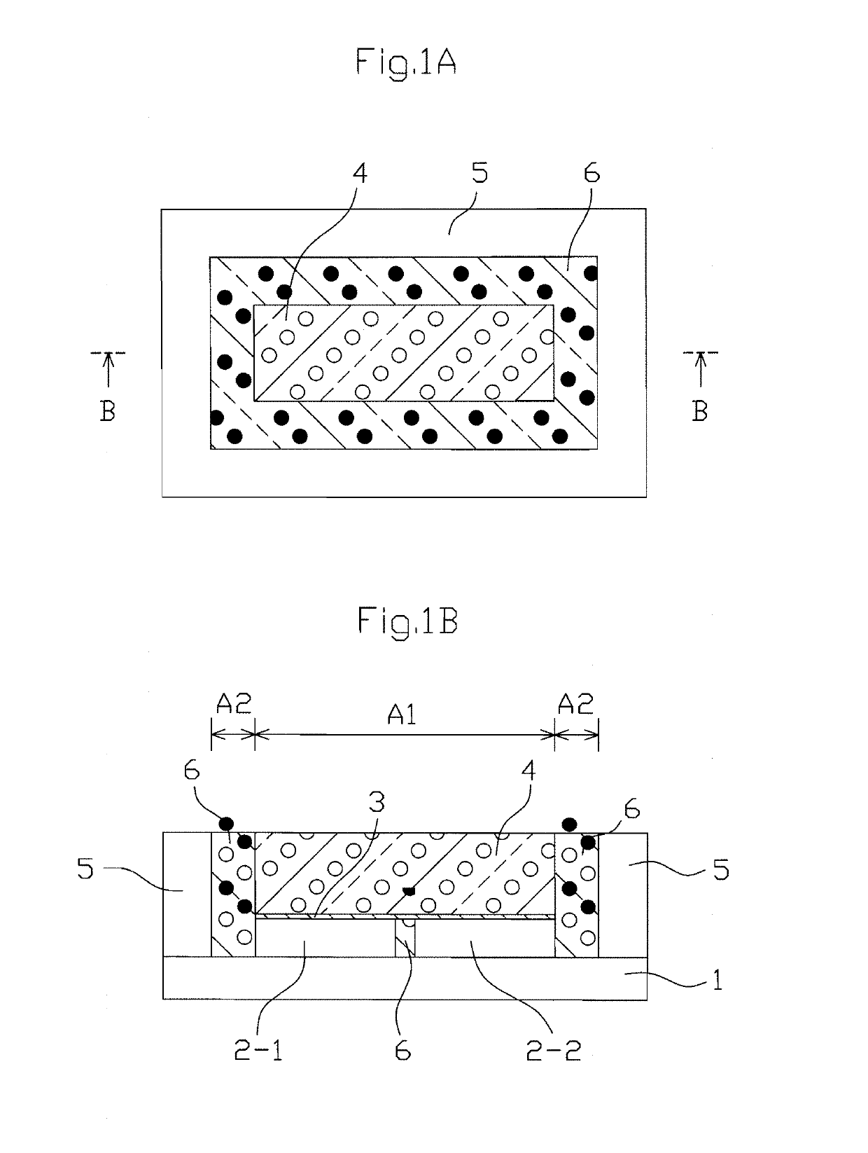
[0038]FIG. 1A is a plan view illustrating a first embodiment of the white-light LED apparatus according to the presently disclosed subject matter, and FIG. 1B is a cross-sectional view taken along the line B-B in FIG. 1A.

[0039]In FIGS. 1A and 1B, the white-light LED apparatus is constructed by a wiring substrate 1, two blue-light LED elements 2-1 and 2-2 mounted on the wiring substrate 1, a wavelength-converting element (plate) 4 adhered via a transparent adhesive layer 3 to the blue-light LED elements 2-1 and 2-2, a frame 5 surrounding the peripheries of the blue-light LED elements 2-1 and 2-2 and the wavelength-converting member 4, and a coverage member of a light reflection adjusting member 6 provided between the blue-light LED elements 2-1 and 2-2 and the frame 5 and between the wavelength-converting element 4 and the frame 5. That is, the light reflection adjusting member 6 directly covers the sidewalls of the blue-light LED elements 2-1 and 2-2 and the wavelength-converting el...

Example

[0052]FIG. 4A is a plan view illustrating a second embodiment of the white-light LED apparatus according to the presently disclosed subject matter, and FIG. 4B is a cross-sectional view taken along the line B-B in FIG. 4A.

[0053]In FIGS. 4A and 4B, the blue-light LED elements 2-1 and 2-2 of FIGS. 1A and 1B are replaced by one blue-light LED element 2, and the size of the wavelength-converting member (plate) 4 is smaller than that of the blue-light LED element 2 viewed from the top. In this case, the transparent adhesive layer 3 is skirt-shaped or fillet-shaped to cover a part of the upper surface of the blue-light LED element 2 and a part of the sidewall of the wavelength-converting element 4. Since the size of the wavelength-converting element 4 is smaller than that of the blue-light LED element 2 viewed from the top, the light emitted from the blue-light LED element 2 is effectively introduced via the fillet-shaped transparent adhesive layer 3 into the wavelength-converting element...

Example

[0056]FIG. 5A is a plan view illustrating a third embodiment of the white-light LED apparatus according to the presently disclosed subject matter, and FIG. 5B is a cross-sectional view taken along the line B-B in FIG. 5A.

[0057]In FIGS. 5A and 5B, the wavelength-converting plate 4 is skirt-shaped or fillet-shaped. That is, the size of the lower surface of the wavelength-converting plate 4 is about the same as the size of the light-emitting area A1 of the blue-light LED elements 2-1 and 2-2 including the gap therebetween viewed from the top. On the other hand, the size of the upper surface of the wavelength-converting plate 4 is smaller than that of the blue-light LED elements 2-1 and 2-2 viewed from the top. In more detail, the sidewall of the wavelength-converting plate 4 is constructed by a lower vertical section 4-1 in proximity to the lower surface, an upper vertical section 4-2 in proximity to the upper surface, and a sloped section 4-3 between the lower vertical sections 4-1 an...


PUM


Abstract

A semiconductor light-emitting apparatus is constructed by a wiring substrate, at least one semiconductor light-emitting element provided on the wiring substrate, at least one wavelength-converting member provided on the semiconductor light-emitting element, and a light reflection adjusting member directly covering a sidewall of the semiconductor light-emitting element and a sidewall of the wavelength-converting member. The light reflection adjusting member is formed of gray resin including light reflecting fillers and light absorbing fillers for visible light.

Description

[0001]This application claims the priority benefit under 35 U.S.C. § 119 to Japanese Patent Application No. JP2018-072290 filed on Apr. 4, 2018, which disclosure is hereby incorporated in its entirety by reference.BACKGROUNDField[0002]The presently disclosed subject matter relates to a semiconductor light-emitting apparatus such as a white-light light-emitting diode (LED) apparatus and its manufacturing method.Description of the Related Art[0003]Generally, a semiconductor light-emitting apparatus such as a white-light LED apparatus is used as an illumination apparatus such as a vehicle headlamp, a street lamp or a conventional lamp.[0004]A first prior art white-light LED apparatus is constructed by a wiring substrate, a blue-light LED element provided on the substrate, a wavelength-converting member made of phosphor provided on the upper surface of the blue-light LED element for converting a part of the blue light emitted by the blue-light LED element into wavelength-converted light...

Claims


Application Information

Patent Timeline
IPC IPC(8): H01L33/60H01L25/075
CPCH01L25/0753H01L33/60H01L33/507H01L2933/0058H01L33/502H01L2933/0041H01L33/56H01L33/46H01L33/44H01L33/505
Inventor HARADA, MITSUNORITACHIBANA, KAORIANDO, SATOSHI
Owner STANLEY ELECTRIC CO LTD
Why Eureka
Try Eureka