Led light source and image reading apparatus

a technology of led light source and image reading device, which is applied in the direction of lighting and heating apparatus, instruments, optical elements, etc., can solve the problems of limited light guide length, uneven light amount of image as a whole, and sometimes impossible reading

Inactive Publication Date: 2010-08-26
NISCA KK
View PDF15 Cites 15 Cited by
  • Summary
  • Abstract
  • Description
  • Claims
  • Application Information

AI Technical Summary

Benefits of technology

[0069]As a result, as shown in FIG. 15c, the light amount of the LED end portion of the light guide RG is further attenuated, and it is possible to resolve evenness in the light amount in the main scanning line direction.
[0070]As described above, by making adjustments to the

Problems solved by technology

First, the above-mentioned optical reduction type image reading apparatus has the following problem.
As a result, the center portion is bright, the opposite sides are dark, and unevenness develops in the light amount of the image as a whole.
However, this method of providing the slit plate SH is to reduce the entire light-amount level by cutting the amount of received light of the light-receiving means CCD, the whole of the image to read is darkened, and reading is sometimes made impossible due to a lack of the light amount.
Meanwhile, the following problem arises in the above-menti

Method used


Image

  • Led light source and image reading apparatus
  • Led light source and image reading apparatus
  • Led light source and image reading apparatus

Examples


embodiment 2

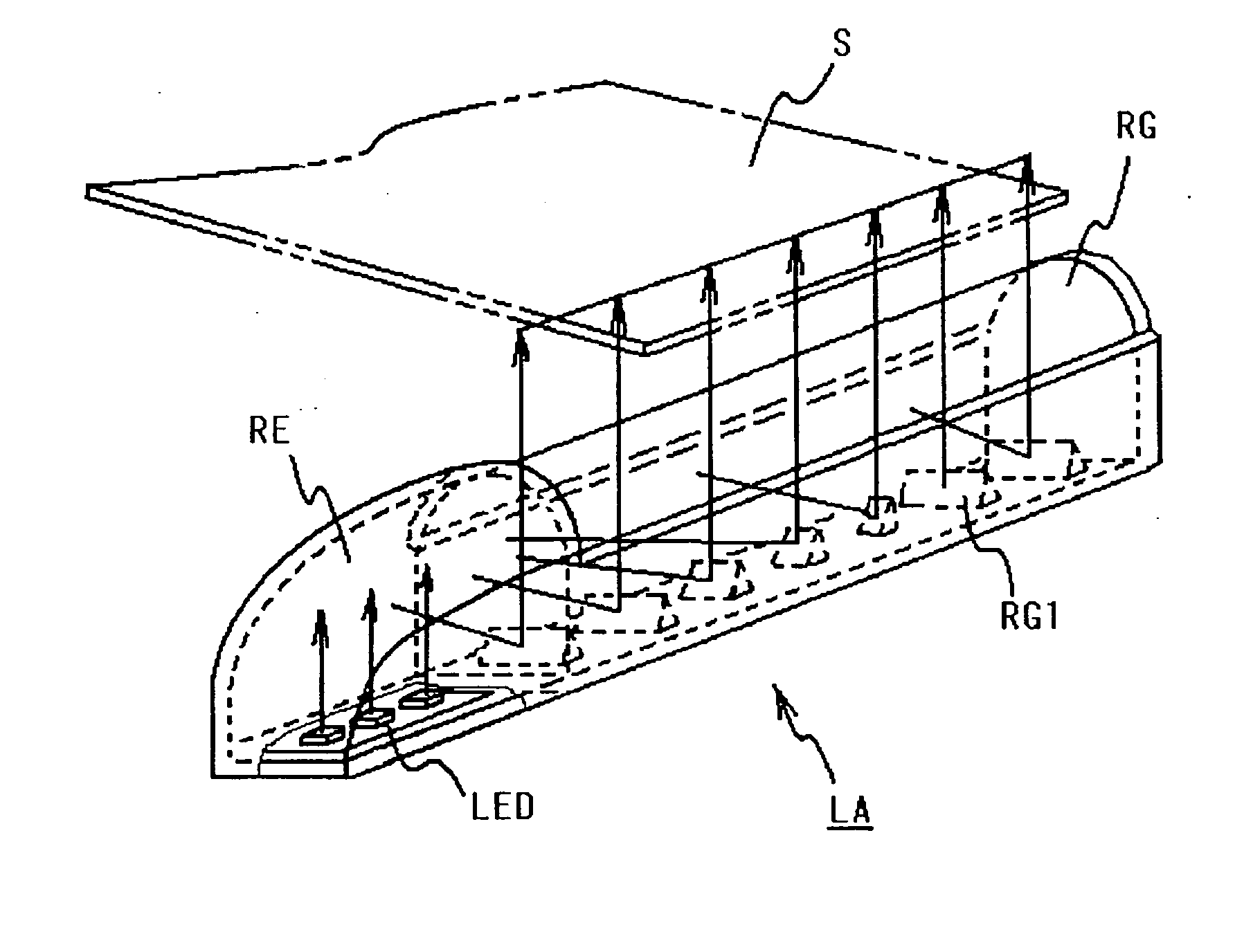
[0061]Embodiment 2 will be described below based on FIGS. 14 and 15. In Embodiment 2, the LED light source of the invention described previously is used as a light source of a contact image sensor type image reading apparatus.

[Configuration and Operation Outline of the Image Reading Apparatus]

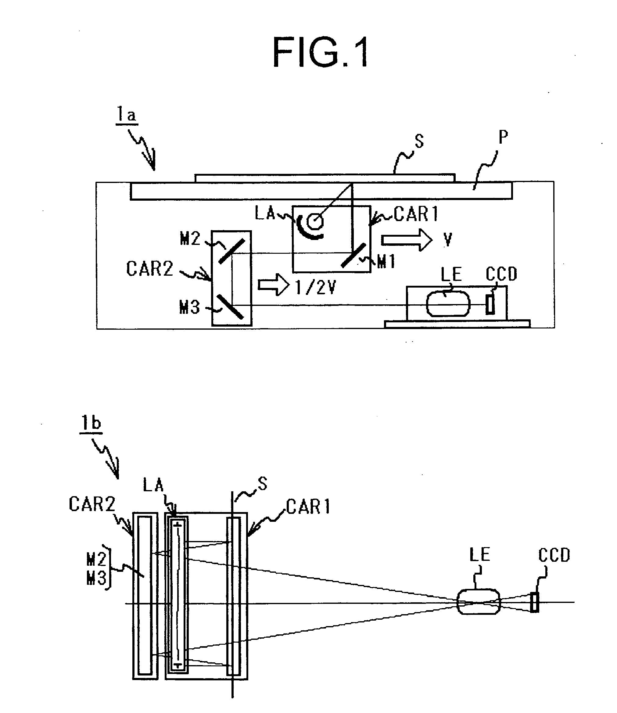
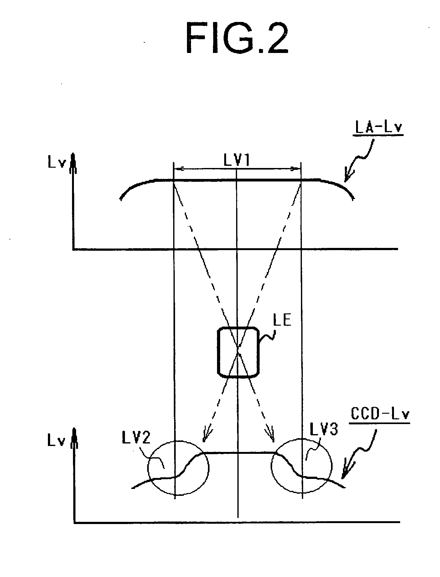
[0062]FIG. 14 contains configuration diagrams showing a schematic configuration of a contact image sensor type image reading apparatus according to the invention, where FIG. 14a is a configuration diagram of the apparatus, and FIG. 14b is a schematic view of the contact image sensor as viewed from the read original side.

[0063]The entire apparatus configuration will be described first based on FIG. 14a. The apparatus is comprised of a platen P for mounting a read original S, and a carriage body having an LED light source LA for lighting an original surface of the read original S placed on a mount surface of the platen P, a Selfoc lens SL for condensing the reflected light from an original surfac...


PUM


Abstract

The present invention provides an LED light source optimal as a light source of image reading apparatuses, and the light source is used in an image reading apparatus comprised of a platen for mounting a read original, a light source for lighting the read original mounted on the platen, a lens means for condensing reflected light from a main scanning line of the read original lighted by the LED light source, and a light-receiving means for receiving the reflected light from the main scanning line of the read original condensed by the lens means, and has an LED that is a light-emitting source, and a light guide for reflecting the light of the LED by an inner surface thereof to diffuse in the shape of the main scanning line, where the LED is disposed in an end portion in the main scanning line direction of the light guide, the light guide has an inner surface opposed to a light-emitting surface of the LED forming a curved reflecting surface for reflecting in the main scanning line direction, the LED is disposed out of a critical angle region at the end in the main scanning line direction of the curved reflecting surface, the light guide has a plurality of reflecting surface bodies spaced at predetermined pitches in the main scanning line direction with the bodies surface-opposed to the LED side inside an inner surface reflection optical path of the light guide to reflect the light of the LED toward the outside of the light guide along the main scanning line, and a length in the perpendicular direction to the main scanning line direction of each of the reflecting surface bodies is adjusted corresponding to a light amount to reflect.

Description

BACKGROUND OF THE INVENTION[0001]The present invention relates to an LED light source with an LED as a light-emitting source used in an image reading apparatus as a light source, and an optical reduction type image reading apparatus using the LED light source as a light source.[0002]Conventionally, as this kind of optical reduction type image reading apparatus, for example, such an apparatus has been known in Patent Document 1 [Japanese Laid-Open Patent Publication No. 2002-101263]. In FIG. 1, as shown in FIG. 1a, the optical reduction type image reading apparatus is comprised of a platen P for mounting a read original S, a first carriage body having a light source LA for lighting an original surface of the read original S placed on a mount surface of the platen P and a reflector M1 for reflecting the reflected light from the original surface of the read original S, a second carriage body having reflectors M2 and M3 for guiding the reflected light of the reflector M1 to a light-rece...

Claims


Application Information

Patent Timeline
IPC IPC(8): F21V7/04F21V9/40
CPCG02B6/0038G02B6/0061H04N1/02885H04N1/02835H04N1/02815
Inventor SAKAMOTO, FUMIHIDEKAGAMI, YUICHITANAKA, SATOSHI
Owner NISCA KK
Why Eureka
Try Eureka