Sewing machines

A sewing machine and needle technology, applied in the field of sewing machines, achieves the effects of simple mechanism, improved reliability and reduced processing time

Inactive Publication Date: 2003-09-03
JUKI CORP
View PDF1 Cites 5 Cited by
  • Summary
  • Abstract
  • Description
  • Claims
  • Application Information

AI Technical Summary

Problems solved by technology

However, when the length from the needle hole of the needle 105 to the end of the upper thread is too long, the end of the upper thread such as Figure 11 As shown in part A of , it will be exposed from the way of the stitch, so that there is a

Method used


Image

  • Sewing machines
  • Sewing machines
  • Sewing machines

Examples


Embodiment Construction

[0049] Hereinafter, specific embodiments of the present invention will be described with reference to the drawings. However, the scope of the present invention is not limited to the illustrated examples.

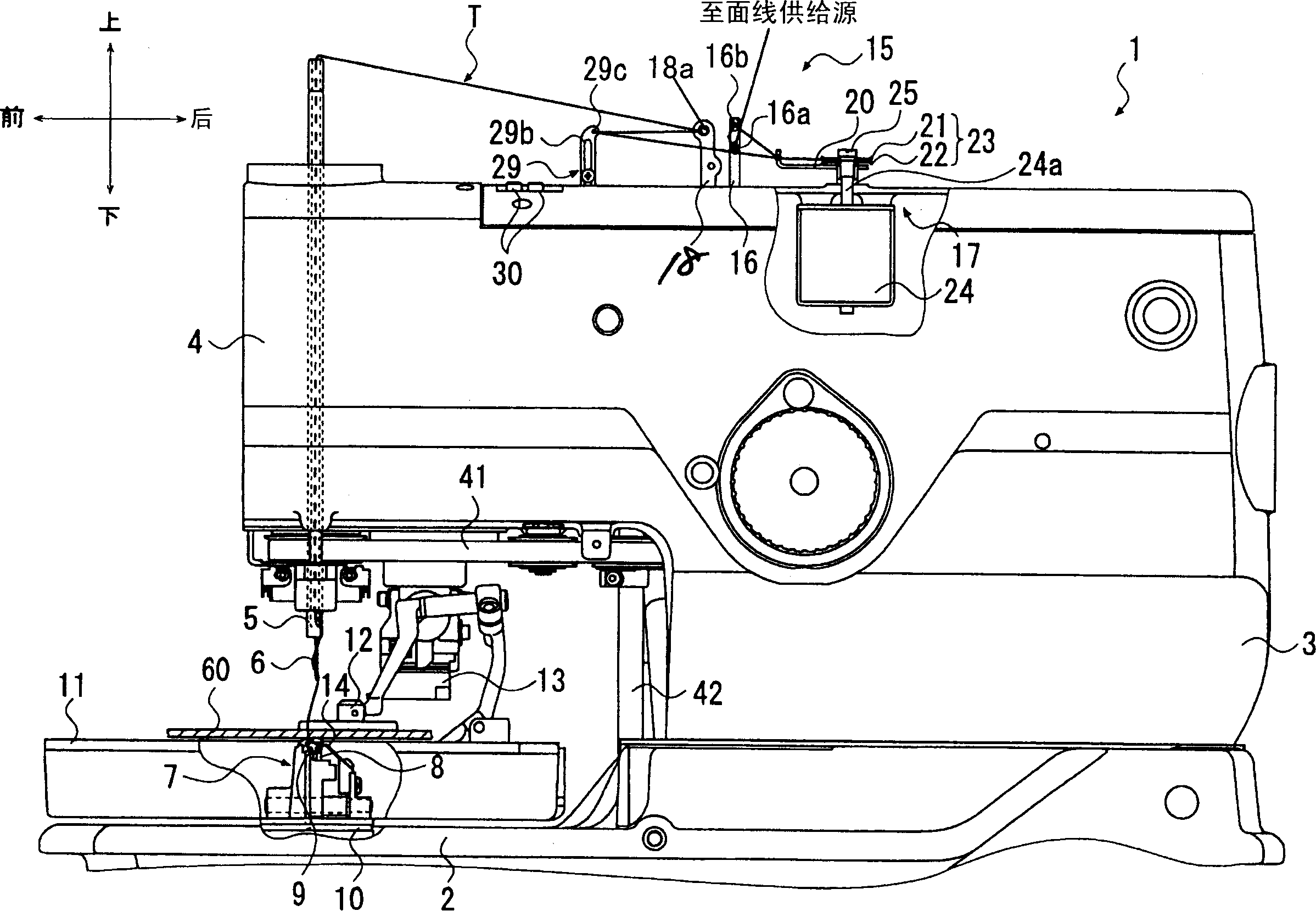
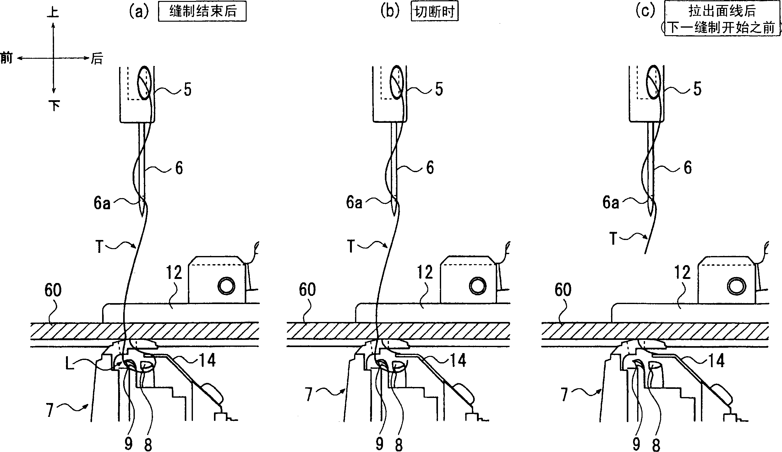
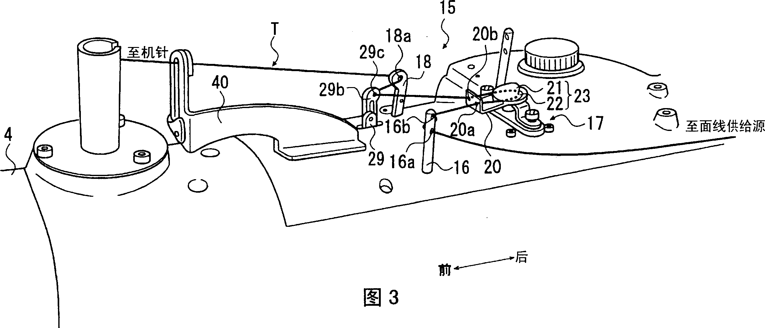
[0050] figure 1 The shown buttonhole sewing machine 1 for buttonhole has a base part 2 in a substantially rectangular box shape, a vertical body part 3 standing upright on the rear end of the frame part 2, and a vertical body part 3 from the vertical body part 3. The upper part of the machine part 2 is slightly parallel to the machine head 4 extending forward, and the needle bar 5 passing through the front end of the machine head 4 up and down, and the machine needle 6 installed on the lower end of the needle bar 5, and The thread shuttle mechanism 7 which is arranged directly below the machine needle 6 in the machine table part 2, and the control device 50 which controls the sewing machine 1 as a whole ( Figure 5 shown).

[0051] A pair of presser feet 12 is provided o...


PUM


Abstract

This sewing machine 1 includes a thread tension device 17 for applying pressing force to the needle thread, a needle thread handling member 29 for handling the needle thread guided from the thread tension device 17, air cylinders 26, 27 for moving the needle thread handling member 29 from the foremost position P10 through the middle position P30 to the last position P20, a needle thread cutting knife 14 for cutting the needle thread, and a control device 50 for controlling the air cylinders 26, 27. The needle thread is guided from the needle thread handling member 29 to a needle thread take-up lever 18 to finally reach a thread passing hole 6a of a needle 6. Immediately before the start of sewing, the needle thread handling member 29 is moved from the foremost position P10 to the last position P20. After the end of sewing, the needle thread handling member 29 is moved from the last position P20 to the middle position P30. After that, the pressing force to the needle thread is increased by the thread tension device. Subsequently, the needle thread handling member 29 is moved from the middle position P30 to the foremost position P10.

Description

technical field [0001] The present invention relates to a sewing machine with a thread cutting device for cutting the upper thread connected to the needle hole of the sewing object after sewing. Background technique [0002] So, on a sewing machine with a thread trimming device, when the upper thread needs a stronger tension when the sewing machine starts to sew, when the needle drops at the beginning of sewing, the upper thread will be pulled out from the upper thread supply source, Therefore, the end of the upper thread will be pulled out from the needle hole, or the upper thread will not be caught when the upper thread falls off the way of the hook, so it is difficult to form a stitch of one stitch, resulting in skipped threads. [0003] Therefore, on conventional sewing machines, before the thread is cut off after sewing, the upper thread should be slack between the thread adjusting device and the hole of the needle, so that thread skipping can be prevented during the ne...

Claims


Application Information

Patent Timeline
IPC IPC(8): D05B65/06D05B3/08D05B45/00D05B47/04D05B49/00D05B53/00D05B65/02
CPCD05B47/04D05B49/00D05B65/02D05B19/00
Inventor 日塔隆
Owner JUKI CORP
Why Eureka
Try Eureka