Lower shaft driving mechanism of sewing machine

A technology of sewing machine and shaft drive, applied in the direction of sewing machine components, sewing machine control devices, sewing equipment, etc.

Inactive Publication Date: 2003-09-03
JUKI CORP
View PDF0 Cites 9 Cited by
  • Summary
  • Abstract
  • Description
  • Claims
  • Application Information

AI Technical Summary

Problems solved by technology

[0016] For this reason, the lower shaft 7 of the lower shaft drive me

Method used


Image

  • Lower shaft driving mechanism of sewing machine
  • Lower shaft driving mechanism of sewing machine
  • Lower shaft driving mechanism of sewing machine

Examples


Embodiment Construction

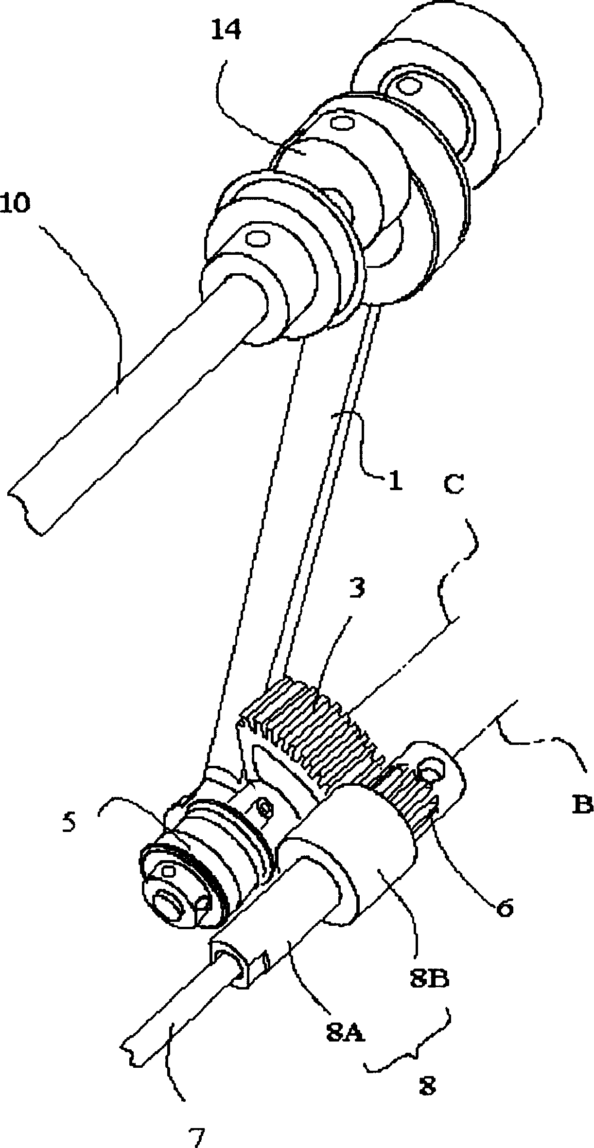
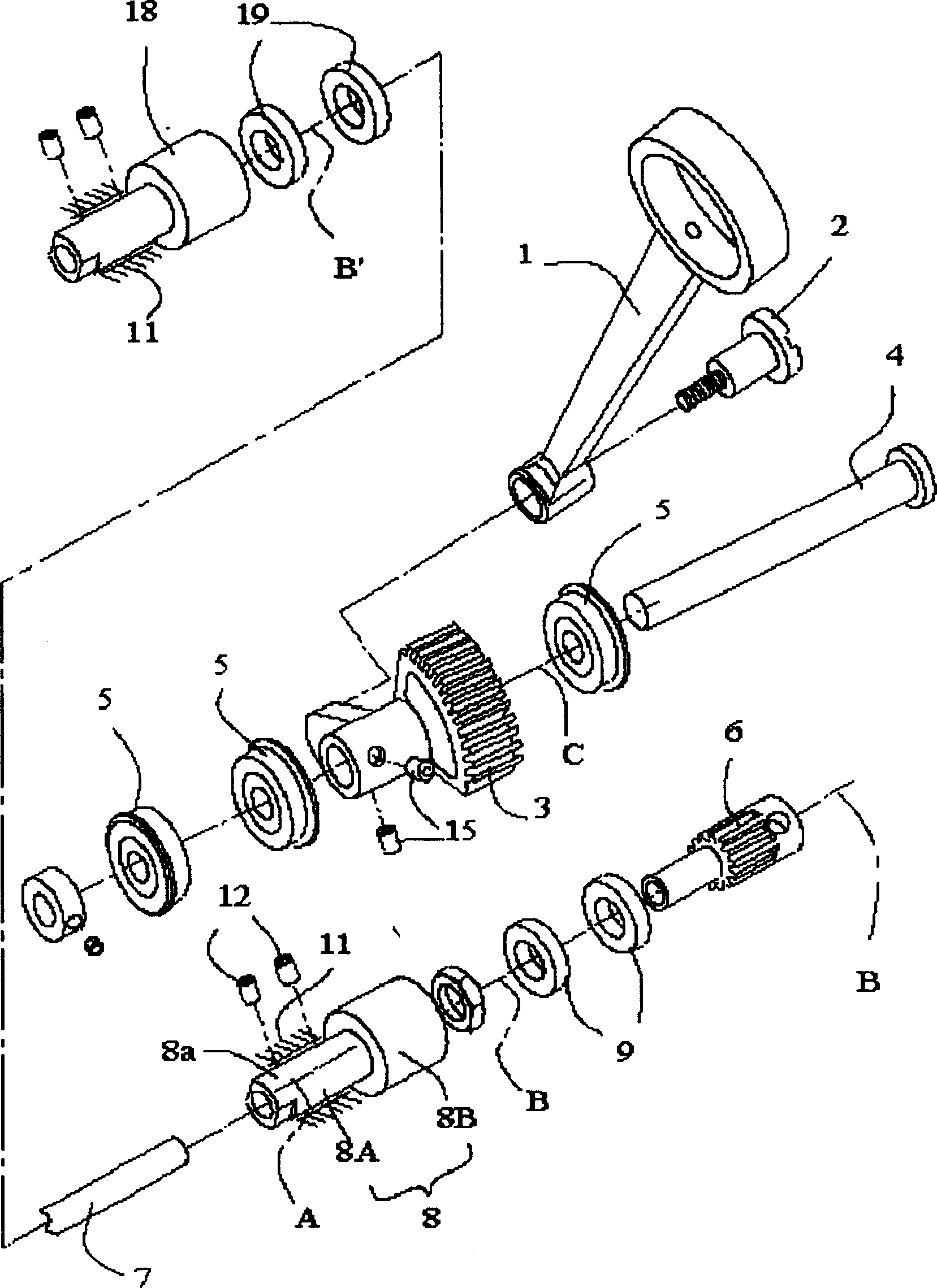
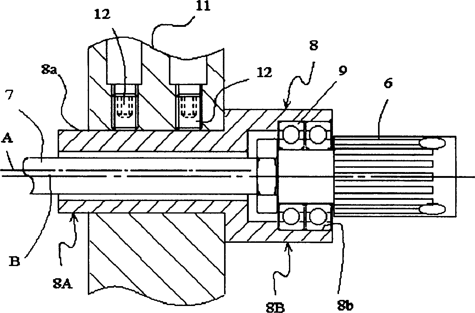
[0025] Below, refer to figure 1 — Figure 4 Specific examples of the present invention will be described. According to the lower shaft driving mechanism of the sewing machine of the present embodiment, there are crank rod (conversion mechanism) 1, large swing pin 2, large swing gear 3, large swing shaft 4, large swing bearing 5, lower shaft gear 6, lower shaft 7, Lower shaft sleeve 8, lower shaft bearing 9 and upper shaft 10 etc. This sewing machine is a semi-rotary rotary hook sewing machine, and its lower shaft 7 does not rotate in a full circle, but swings and rotates in a range of more than 200 degrees, for example, 220 degrees.

[0026] The upper end of the crank rod 1 is connected to the upper shaft 10 through the eccentric cam 14 , and the lower end is swingably connected to the large swing gear 3 through the large swing pin 2 . The large swing gear 3 is fixed on the large swing shaft 4 with fastening screws 15, and the two ends of the large swing shaft 4 are swinga...


PUM


Abstract

The patent relates to a lower shaft driving mechanism without oil-feed structure in a sewing machine having a lower shaft performing rocking motion, which has a converting means 1 for converting the rotary motion of an upper shaft 10 to a rocking motion, a rocking rotator connected to the converting means and having a large pendulum gear 3 rockably rotating around a large pendulum shaft supported on a sewing machine frame, and a lower shaft 7 where a lower shaft gear 6 meshing with the large pendulum gear is fixed and rotary motion of the upper shaft is transmitted by both gears to rockably rotate. The present invention is characterized in that the mechanism has a bearing 8, the outer periphery of which is fixed to the sewing machine frame 11, and the gear side of the lower shaft is rotatably supported on the inner periphery thereof. The outer periphery of the bearing is formed cylindrical with eccentricity to the shaft center of the inner periphery, and the bearing where the lower shaft is passed is rotated with respect to the sewing machine frame to thereby adjust backlash of the large pendulum gear and the lower shaft gear.

Description

technical field [0001] The invention relates to a lower shaft driving mechanism of a sewing machine with a large pendulum gear and a lower shaft gear and swings, in particular to a lower shaft driving mechanism of a sewing machine capable of adjusting the backlash between the large pendulum gear and the lower shaft gear. Background technique [0002] by Figure 5 A conventional lower shaft drive mechanism that transmits the rotation of the upper shaft to the lower shaft will be described as an example. This conventional example is a drive mechanism in which the lower shaft does not make a full-circle rotation but swings, and has a large swing shaft 104 and a lower shaft 107 arranged in parallel to the upper shaft (not shown). [0003] The large pendulum shaft 104 is composed of three parts having two ends 104a, 104b on the outer periphery on the same axis D and a central part 104c having an outer periphery on the axis E eccentric to the two ends. Parts 104a, 104b are fixed ...

Claims


Application Information

Patent Timeline
IPC IPC(8): D05B69/30D05B69/02D05B71/00
Inventor 日塔隆皆川忠义
Owner JUKI CORP
Why Eureka
Try Eureka