Supercharge Your Innovation With Domain-Expert AI Agents!

Sucking and brushing part with roller used for cleaning dust

A technology of rotating parts and parts, applied in the direction of suction nozzles, applications, vacuum cleaners, etc., can solve the problem of weakening of striking performance, and achieve the effect of improving the effect of dust removal

Inactive Publication Date: 2003-09-17
SAMSUNG GWANGJU ELECTRONICS CO LTD
View PDF0 Cites 1 Cited by
  • Summary
  • Abstract
  • Description
  • Claims
  • Application Information

AI Technical Summary

Problems solved by technology

As a result, all the protrusions hit the fabric, resulting in less effective hitting

Method used


Image

  • Sucking and brushing part with roller used for cleaning dust
  • Sucking and brushing part with roller used for cleaning dust
  • Sucking and brushing part with roller used for cleaning dust

Examples


Embodiment Construction

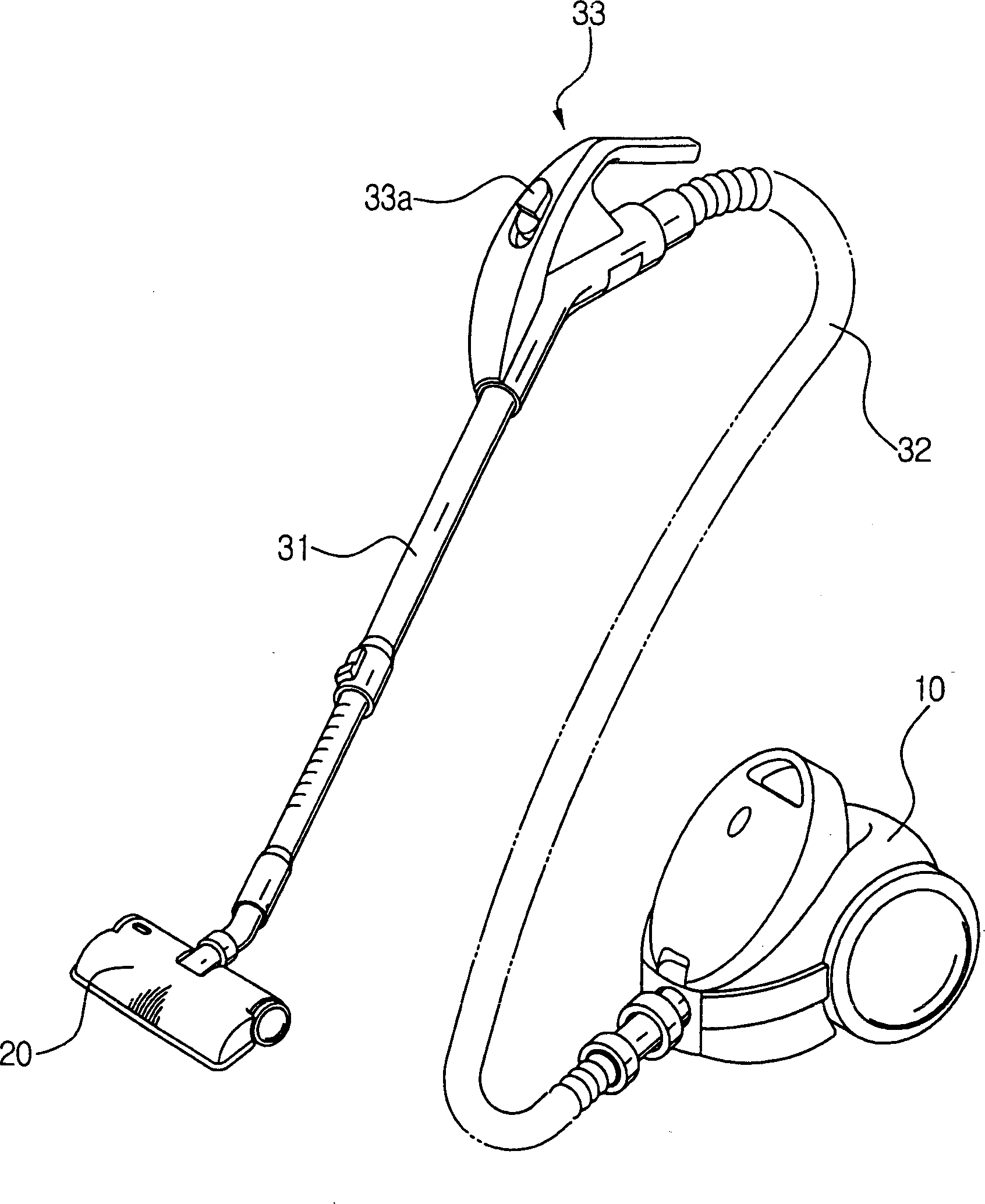
[0020] Preferred embodiments of the present invention will be described in detail below in conjunction with the accompanying drawings. In the drawings, whenever possible, the same reference numerals denote the same or similar elements in different drawings. In the description of the present invention, the figure 1 A description of each part of the shown conventional vacuum cleaner will be omitted.

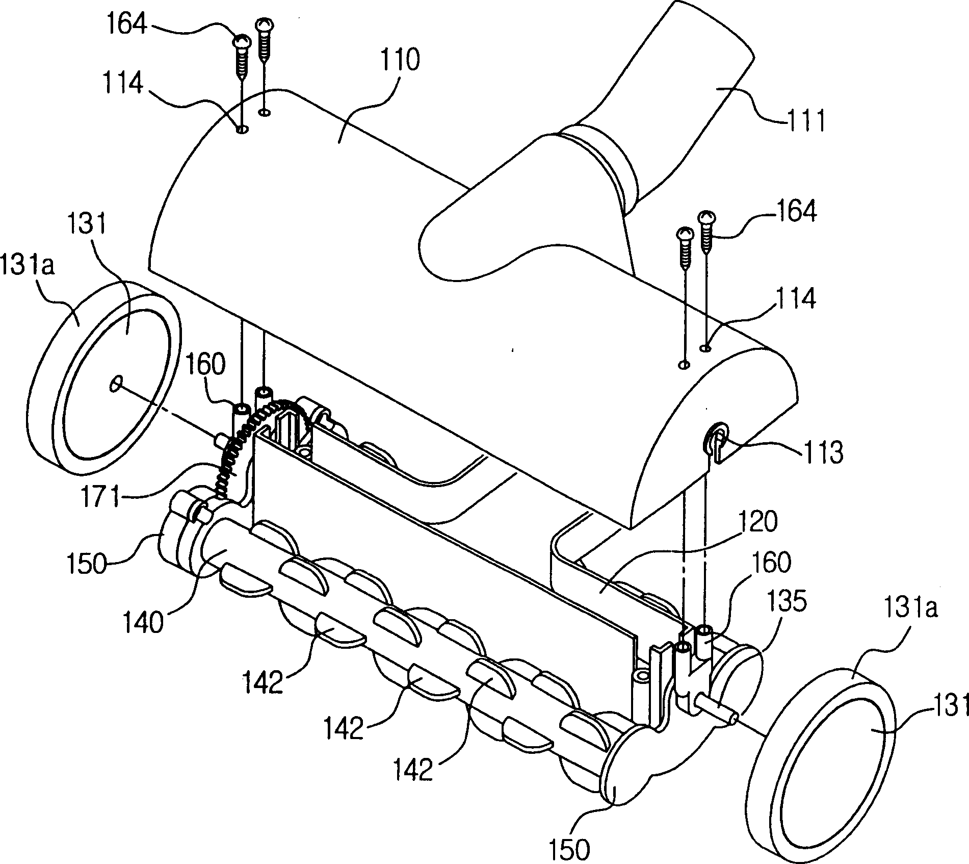
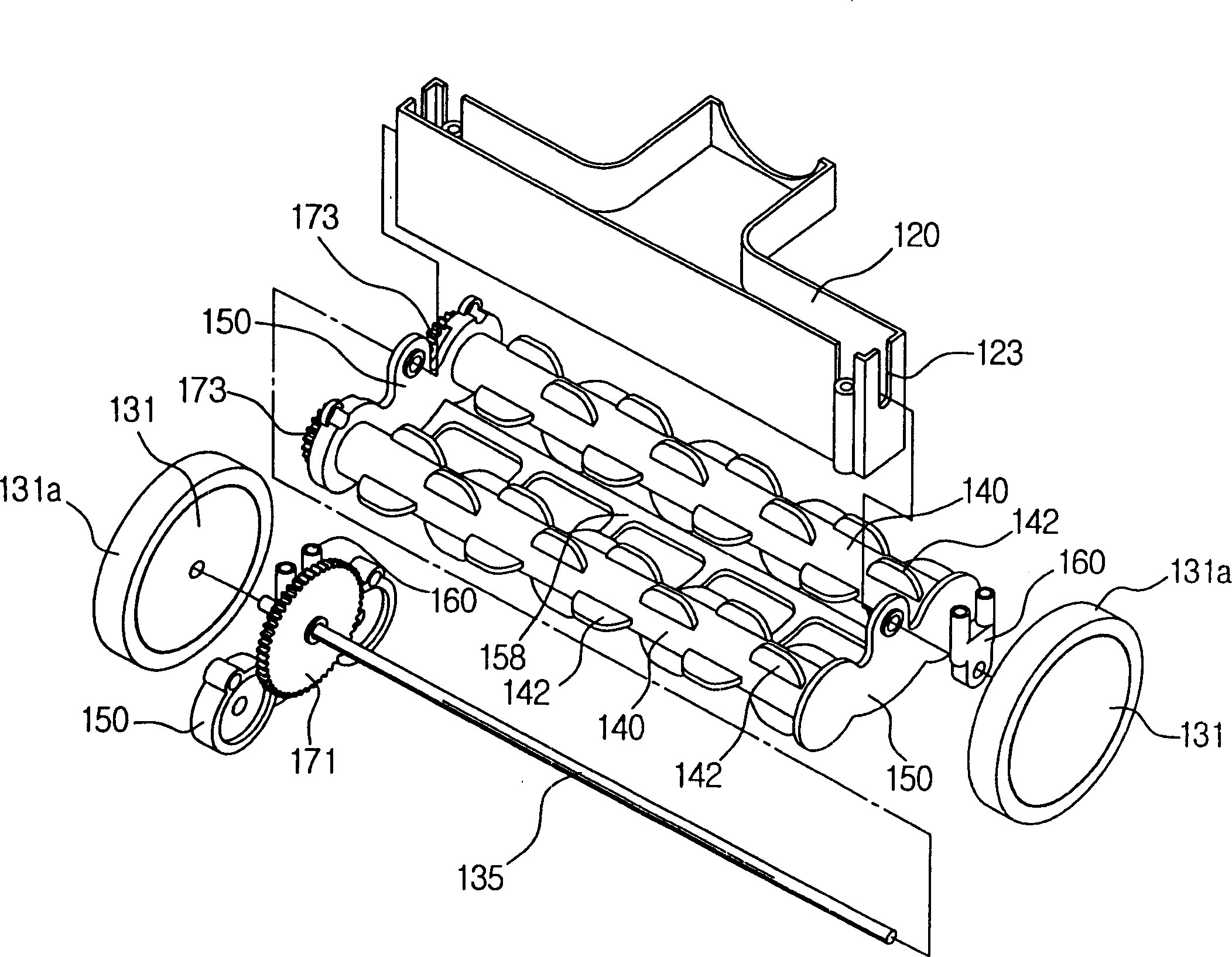
[0021] figure 2 and image 3 is an exploded perspective view of a suction brush unit according to the present invention. The suction brush part has a housing 110 connected with a vacuum cleaner extension tube (not shown), a pair of rotating rollers 140 disposed on the lower part of the housing 110, and a pair of wheels 131 disposed on both sides of the housing 110.

[0022] The casing 110 has a connecting pipe 111 connected together with an extension pipe of a vacuum cleaner. The duct part 120 is installed at the lower portion of the housing 110 . The duct part 120 and the h...


PUM


Abstract

A suction brush part of a vacuum cleaner includes a housing with a suction pipe providing a suction path for dust, a plurality of raised rotating rollers formed on its outer circumference, wheels arranged on the housing, and a power transmission unit, when the wheels When rotating, the power transmission unit rotates the rotating member by applying the rotating force of the wheel to the rotating member. The wheels and the rotating member are rotated in opposite directions to each other by the power transmission unit. When the user wants to clean fabrics such as bedspreads or carpets, the impact effect of the ribs can be ensured due to the rotation of the rollers. As a result, the dust removal effect is significantly improved.

Description

technical field [0001] The present invention relates to a vacuum cleaner, and more particularly to a suction brush unit having a roller for cleaning dust from bedspreads and the like, and a vacuum cleaner having such a unit. Background technique [0002] figure 1 It is a schematic diagram showing the appearance of a conventional vacuum cleaner. A conventional vacuum cleaner includes a main body 10 having a driving device such as a motor, a connecting hose 32 connected to the main body 10, a handle 33 provided on the end of the connecting hose 32, an extension pipe 31 provided on the handle 33, and The brush 20 arranged at the end of the extension tube 31. When the user drives the vacuum cleaner by manipulating the switch 33a provided on the handle 33, the vacuum cleaner performs a dust collection operation when the motor in the main body 10 is driven. Therefore, the dust is sucked into the vacuum cleaner through the suction port formed at the bottom of the brush 20 . The...

Claims


Application Information

Patent Timeline
Patent Type & Authority Applications(China)
IPC IPC(8): A47L9/02A47L5/34A47L9/04
CPCA47L5/34A47L9/0411A47L9/0433A47L9/0488A47L9/0494A47L9/02
Inventor 周诚泰吴长根
Owner SAMSUNG GWANGJU ELECTRONICS CO LTD
Features
  • R&D
  • Intellectual Property
  • Life Sciences
  • Materials
  • Tech Scout
  • Unparalleled Data Quality
  • Higher Quality Content
  • 60% Fewer Hallucinations
Learn More