Method for making modular energy-absorbing assembly

An energy absorption component, energy absorption technology, used in vehicle components, household components, applications, etc.

Inactive Publication Date: 2003-09-17
OAKWOOD ENERGY MANAGEMENT
View PDF3 Cites 12 Cited by
  • Summary
  • Abstract
  • Description
  • Claims
  • Application Information

AI Technical Summary

Problems solved by technology

However, most of these materials absorb less energ

Method used


Image

  • Method for making modular energy-absorbing assembly
  • Method for making modular energy-absorbing assembly
  • Method for making modular energy-absorbing assembly

Examples


Embodiment Construction

[0036] Before disclosing the manufacturing process steps implemented in accordance with the principles of the present invention, various products and their quality characteristics are first disclosed.

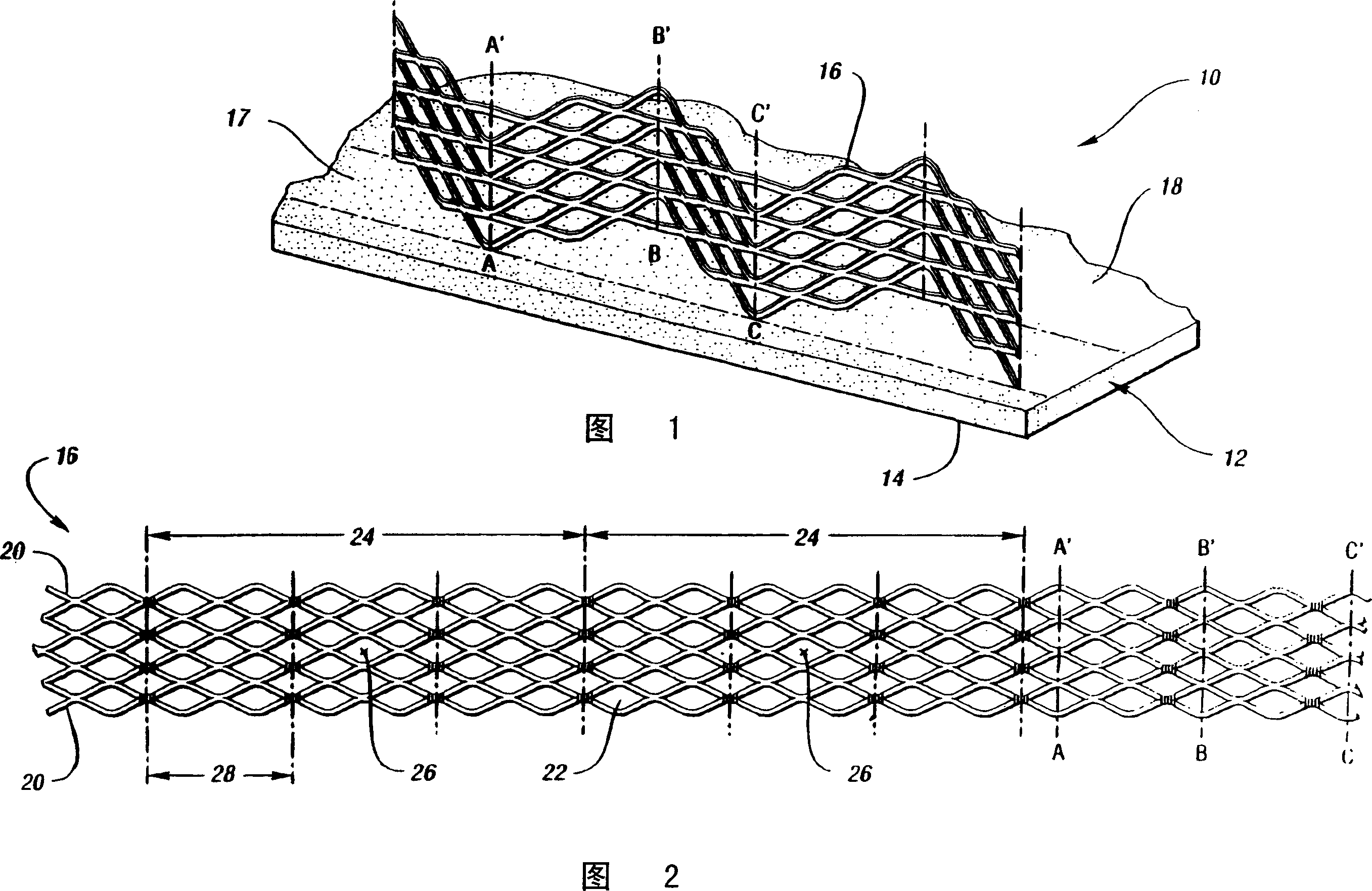
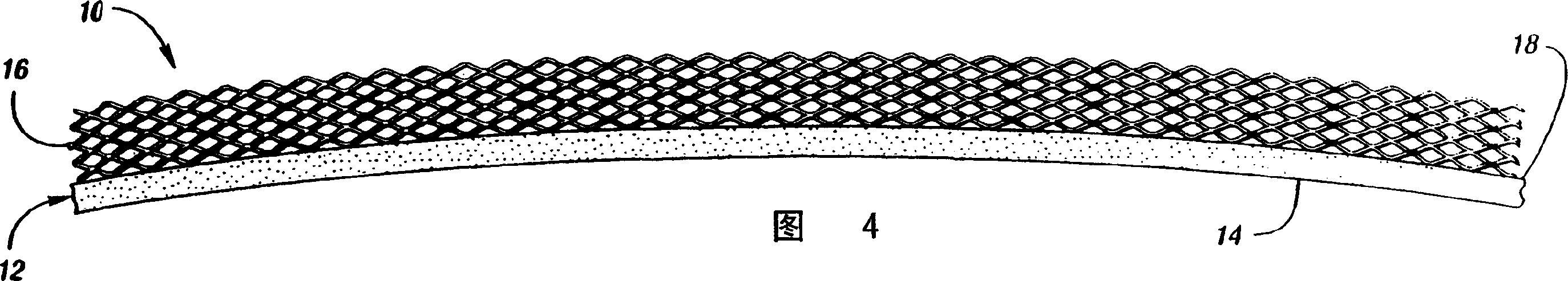
[0037] Referring first to Figure 1, there is shown an energy absorbing assembly 10 made in accordance with the steps of the present invention for decelerating an object (not shown) impinging on the assembly. In the preferred embodiment, the assembly 10 includes an accident component 12 having an accident surface 14 in contact with an impacting object. At least one energy absorbing member 16 is connected to a connection area 17 of the opposite face 18 of the accident member 12 for receiving the deformation of the assembly 10 .

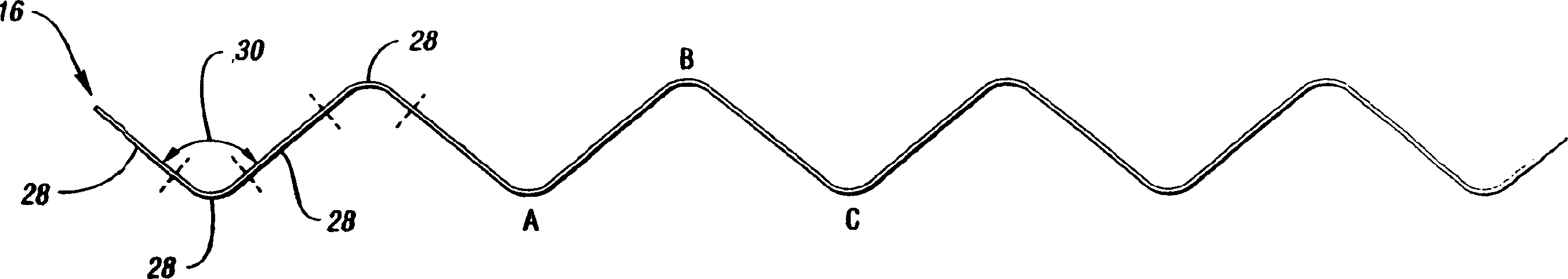
[0038] Referring now to FIG. 2 , each energy absorbing member 16 includes a grid structure of interconnected strands 20 of material, such as expanded metal, that provide the assembly 10 with unique energy absorbing properties. The energy absorbing membe...


PUM


Abstract

A method of making an energy absorbing assembly for decelerating an object striking the assembly. The assembly includes a chassis and at least one energy absorbing module associated therewith. In order to provide predetermined energy absorbing properties, at least one energy absorbing module is made of a structure comprising a first structure (A) and a second structure (B). Structure (A) is a metal grid structure supported by a base plate. Structure (B) includes a plurality of grooves each having a bottom and walls. Taken together, structure (A) and structure (B) and combinations thereof provide the user with the ability to determine impact resistance.

Description

technical field [0001] The present invention relates to a method of manufacturing a modular energy absorbing component for decelerating an object striking the component or an assembly in which the component is placed. Background technique [0002] In many cases it is desirable to provide components which are capable of decelerating objects striking the component for a given limited distance. To do this, the assembly must absorb most of the impact energy transmitted by the object. In the past, this has been accomplished by providing the assembly with energy absorbing components that support the deformation of the assembly to absorb the energy impacting the object. Alternative methods are exemplified in commonly owned US Patent No. 5,700,545, US Serial No. 09 / 018,666, filed February 24, 1998 (now US Patent No. 6,017,084), and June 8, 1999 US Serial No. 09 / 328,196, which is incorporated herein by reference. [0003] In automobiles, for example, passengers need to be protecte...

Claims


Application Information

Patent Timeline
IPC IPC(8): B29C51/08B29C51/10B29C51/12B29C51/14B29C51/30B29C51/44B29L31/58B60R21/04
CPCB29C51/10B29C51/12B29C51/14B29C2791/006B29C2791/007B29L2009/00B29L2031/3044B29L2031/721B60R21/04B60R2021/0414B60R2021/0421B60R2021/0435B29C51/00
Inventor P·P·卡罗尔三世J·M·科尔米尔
Owner OAKWOOD ENERGY MANAGEMENT
Why Eureka
Try Eureka