Bumper assembly and manufacturing method thereof

a technology of bumper assembly and manufacturing method, which is applied in the direction of bumpers, elastic dampers, manufacturing tools, etc., can solve the problems of deterioration of yield, limited product shape, and relatively expensive manufacturing method of such a bumper assembly, so as to reduce or eliminate the variation in manufacturing quality due to bolting and welding, the effect of maximizing collision energy absorption

Inactive Publication Date: 2019-11-21
HYUNDAI MOTOR CO LTD +1
View PDF0 Cites 5 Cited by
  • Summary
  • Abstract
  • Description
  • Claims
  • Application Information

AI Technical Summary

Benefits of technology

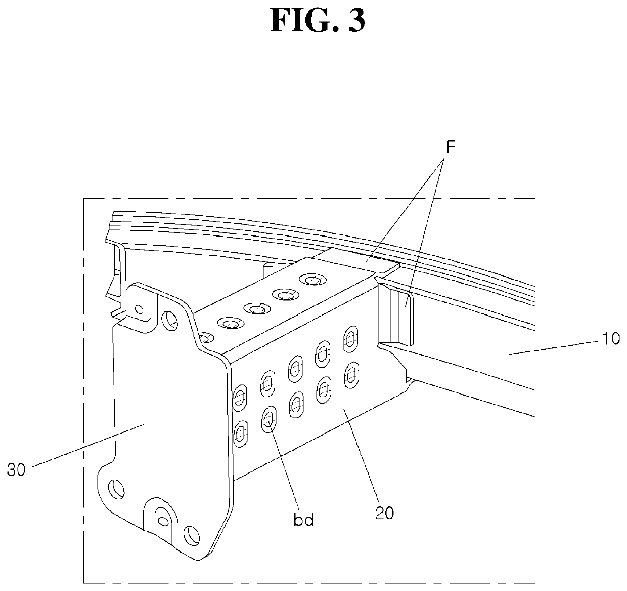
[0012]In accordance with a bumper assembly and a manufacturing method thereof according to exemplary embodiments of the present disclosure, an amount of collision energy absorption may be maximized by implementing beads on the collision box surface by the electro magnetic pulse tech. method. Furthermore, manufacturing quality variation due to bolting and welding may be reduced or eliminated by replacing melting welding with the electro magnetic pulse tech. method.

Problems solved by technology

However, when a substantial collision energy that the energy absorber is unable to bear is generated, the back beam becomes a cross member of a vehicle to absorb the impact energy.
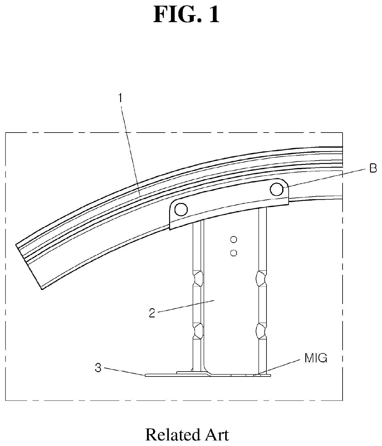
However, the manufacturing method of such a bumper assembly is relatively expensive due to complex processes, product shape is limited, and yield is deteriorated.
Furthermore, although the melting welding (MIG) is performed by automation, welding defects (pore, spatter generation, etc.) are generated depending on the surrounding environment to make the manufacturing quality substantially dispersed.
In addition, since the phase change of the basic material and the filler material (solid→liquid→solid) are accompanied, the welding part and the periphery are subjected to heat to cause the mechanical properties to deteriorate compared to the basic material, thereby requiring a design with additional strength reinforcement.

Method used


Image

  • Bumper assembly and manufacturing method thereof
  • Bumper assembly and manufacturing method thereof
  • Bumper assembly and manufacturing method thereof

Examples


Embodiment Construction

[0019]To understand the present disclosure, the operational advantages of the present disclosure, and the objects attained by the practice of the present disclosure, reference should be made to the appended drawings illustrating the exemplary embodiments of the disclosure and the description in the accompanying drawings.

[0020]In describing an exemplary embodiment of the present disclosure, known techniques or repetitive descriptions that may unnecessarily obscure the essence of the present disclosure would be either reduced or omitted from the description thereof.

[0021]It is understood that the term “vehicle” or “vehicular” or other similar term as used herein is inclusive of motor vehicles in general such as passenger automobiles including sports utility vehicles (SUV), buses, trucks, various commercial vehicles, watercraft including a variety of boats and ships, aircraft, and the like, and includes hybrid vehicles, electric vehicles, combustion, plug-in hybrid electric vehicles, h...


PUM

PropertyMeasurementUnit
weightaaaaaaaaaa
weightaaaaaaaaaa
shapeaaaaaaaaaa

Abstract

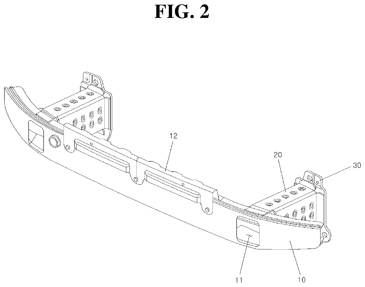
A bumper assembly is provided. The bumper assembly includes a back beam that is disposed within a bumper to absorb an external impact and a collision box that has a hollow tube shape. A first end portion of the collision box is coupled to the back surface of the back beam to receive an impact applied to the back beam and a plate is coupled to a second end portion of the collision box. In particular, the collision box is bonded with the back beam and the plate by an electro magnetic pulse technology method.

Description

CROSS-REFERENCE TO RELATED APPLICATION[0001]The present application claims priority of Korean Patent Application No. 10-2018-0057049 filed on May 18, 2018, the entire contents of which are incorporated herein by this reference.BACKGROUNDField of the Disclosure[0002]The present disclosure relates to bumper assembly mounted on a vehicle and a manufacturing method thereof, and more particularly to a bumper assembly that maximizes collision energy absorption performance.Description of the Related Art[0003]The bumper assembly including a back beam absorbs the collision energy primarily when the vehicle collides with an external object, thereby preventing damage to major components such as an engine and a transmission, and further preventing injury to the vehicle occupant. The bumper is a shock absorber and the bumpers of the vehicle are mounted on the front and the rear, respectively, to protect the vehicle body from external impact. In passenger vehicles, the bumper has been developed t...

Claims


Application Information

Patent Timeline
Patent Type & Authority Applications(United States)
IPC IPC(8): B60R19/18B60R19/34B23K20/06
CPCB23K2101/006B23K2103/10B23K20/06B60R19/34B60R2019/182B60R19/18B60R19/24B60R2019/247F16F7/12
Inventor BAE, CHUL-HONG
Owner HYUNDAI MOTOR CO LTD
Why Eureka
Try Eureka