

Push-button structure and electronic machine and clock with the push-button structure
A button and structure technology, applied in the fields of button structures, electronic machines and timepieces, can solve problems such as difficulty in forming a good design, inability to reduce distance, etc., and achieve the effect of ensuring waterproofness, soft operating force, and slight operating force
- Summary
- Abstract
- Description
- Claims
- Application Information
AI Technical Summary
Problems solved by technology
Method used
Image

Examples
no. 1 example
[0036] Figure 8 It is a schematic vertical cross-sectional view schematically showing the timepiece body 10 of the portable timepiece having the button structure of the present embodiment. Here, the left part of the dashed-dotted line in the center shows the cross section of the watch body at 12 o'clock and 6 o'clock, and the right part of the dashed-dotted line shows the cross section of the watch body at 3 o'clock. The timepiece body 10 has a case 11 ; a display window 12 mounted on the front side of the case 11 ; a back cover 13 mounted on the back side of the case 11 ; and a mechanism 14 accommodated inside the case 11 . The mechanism 14 includes: a display body 141 composed of a pointer, a liquid crystal panel, etc., a circuit board 142, and a power source 143 composed of a general battery, a chemical battery, a large-capacity capacitor, and the like.
[0037] The material of the shell 11 can be metal materials such as stainless steel, titanium alloy, gold alloy, and pl...
no. 2 example
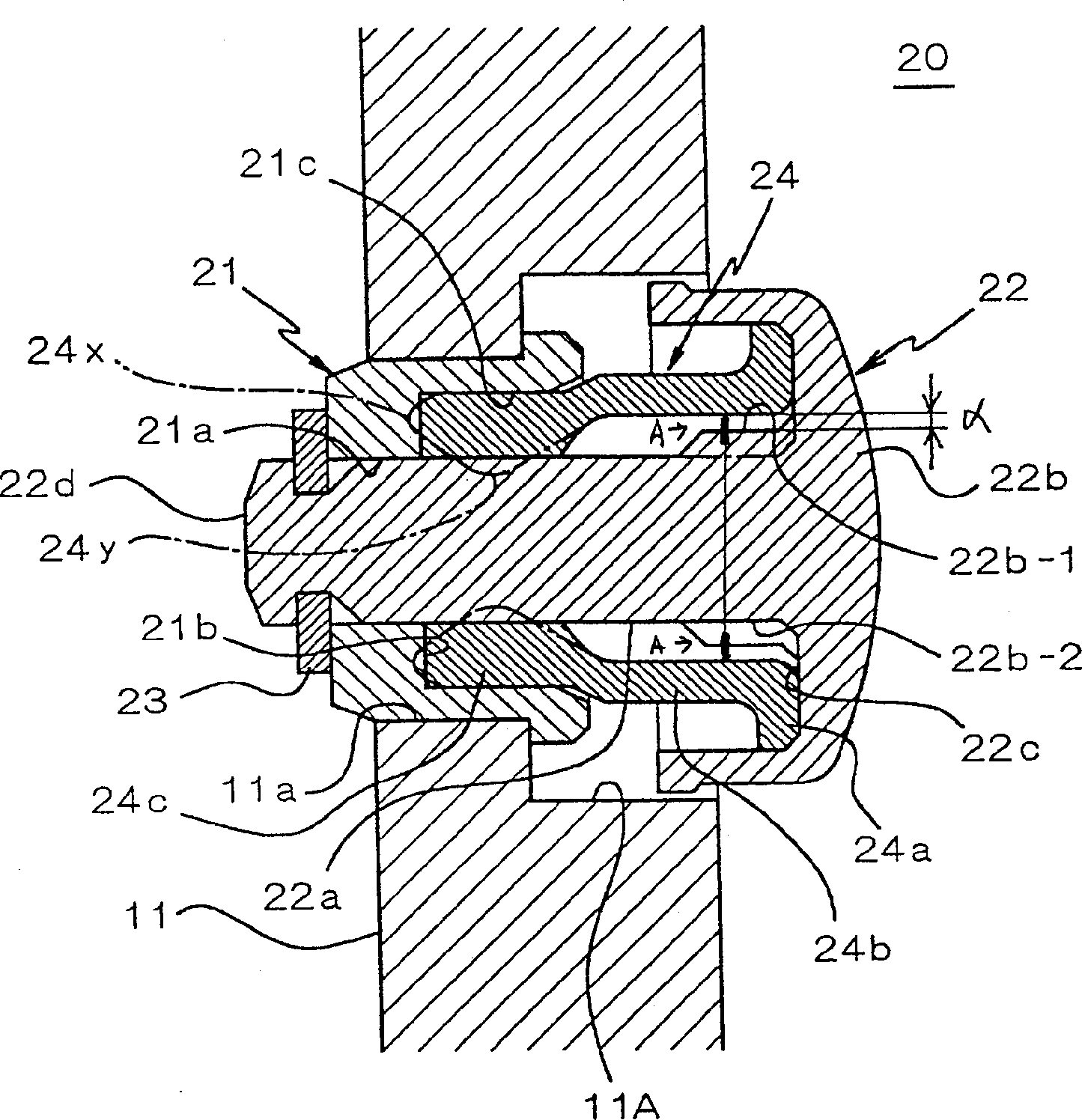
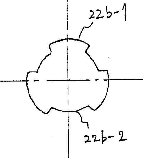
[0054] Refer to the following image 3 , the second embodiment according to the present invention will be described. In the present embodiment, since the operating body 22 and the adapter ring 23 have the same structures as those in the first embodiment, corresponding parts are assigned the same symbols and their descriptions are omitted.
[0055] The tube 21 of the first embodiment is not installed in the casing 11', and the operating body 22 is directly inserted through the through hole 11a'. In the housing 11' itself, formed in the above-mentioned enlarged diameter recess 11A' are: a first surface 11b' composed of an annular plane facing the axial direction; and a second surface 11c' composed of a circular plane facing the radial direction. The inner surface of the cylinder is formed.
[0056] The elastic member 24' is composed of an outer end contact portion 24a', an intermediate portion 24b', and a sealing portion 24c'. Like the first embodiment, the outer end contact ...
no. 3 example
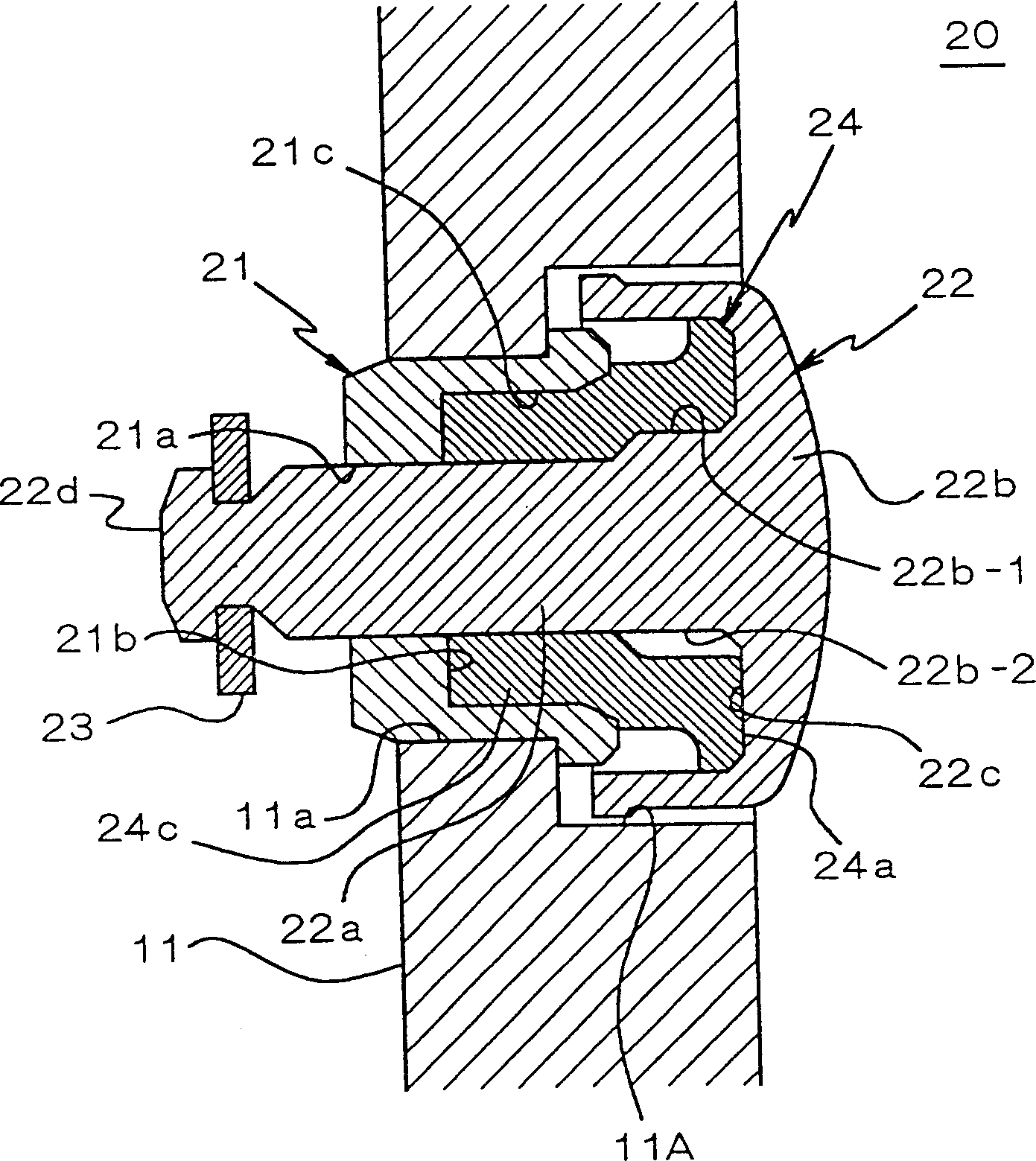
[0061] Refer to the following Figure 4 , to describe the button structure according to the third embodiment of the present invention. Since this button structure has substantially the same structure as the button structure of the above-mentioned second embodiment, the same parts are assigned the same symbols, and description thereof will be omitted.
[0062] This embodiment differs from the second embodiment described above in that the accommodating recessed portion 22c' of the operating body 22' having the shaft portion 22a' and the head portion 22b' faces inward and is formed with a larger width, and as a result, the elastic member 24' The outer end contact portion 24a' is separated from both the inner inner peripheral surface and the outer inner peripheral surface in the accommodation recessed portion 22c'. In this way, by making the outer end contact portion 24a' of the elastic member 24' contact the accommodating recessed portion 22c' with a margin on the inside and out...
PUM
 Abstract
Description
Claims
Application Information