
Digital satellite broadcast receiver

A technology of broadcast receiver and digital satellite, which is applied in satellite broadcast reception, broadcast reception circuit, phase modulation carrier system, etc., and can solve problems such as the best received image.

Inactive Publication Date: 2003-10-15
SHARP KK
View PDF1 Cites 2 Cited by
  • Summary
  • Abstract
  • Description
  • Claims
  • Application Information

AI Technical Summary

Problems solved by technology

However, in this analog satellite broadcast receiver, only the transfer characteristic of the loop filter is changed according to the reception state, so sometimes the received image cannot be optimized depending on the reception state (for example, when the input signal of the FM demodulator When there is a considerably high level due to adjacent interfering waves)

Method used


Image

  • Digital satellite broadcast receiver
  • Digital satellite broadcast receiver
  • Digital satellite broadcast receiver

Examples


Embodiment Construction

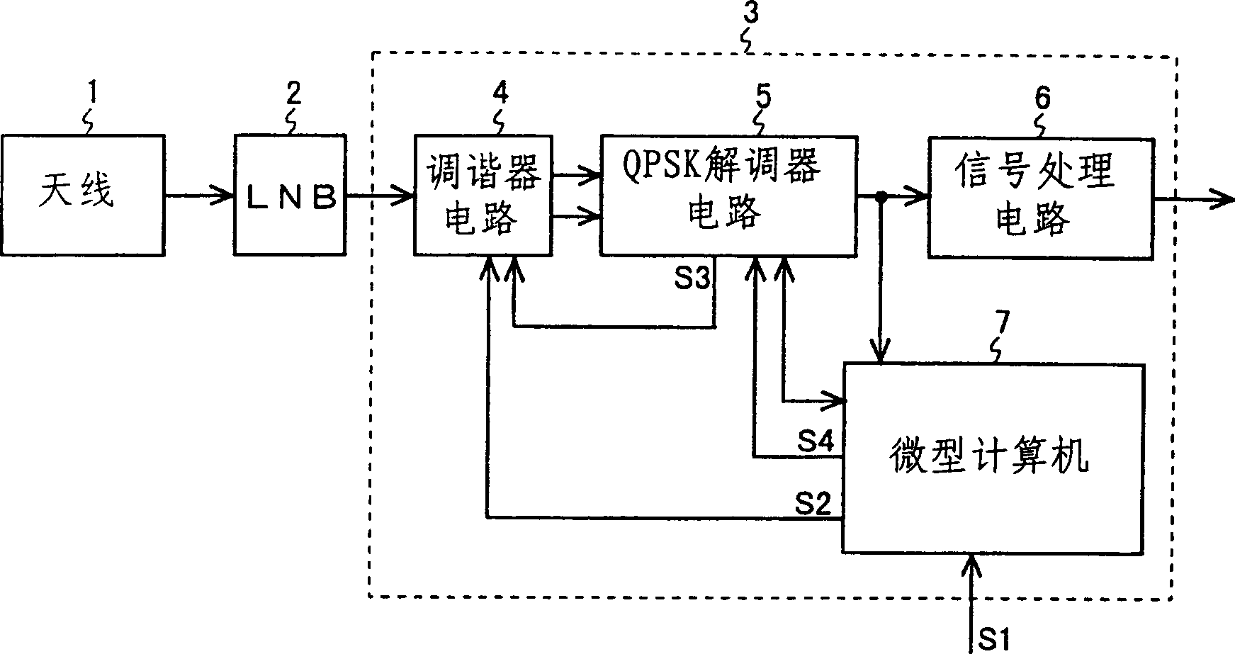
[0023] figure 1 The configuration of a digital satellite broadcast receiver incorporating the present invention is shown. It is worth noting that in figure 1 In , groupings of circuits that are also found in FIG. 5 are identified with the same reference numerals, and their detailed description is not repeated.

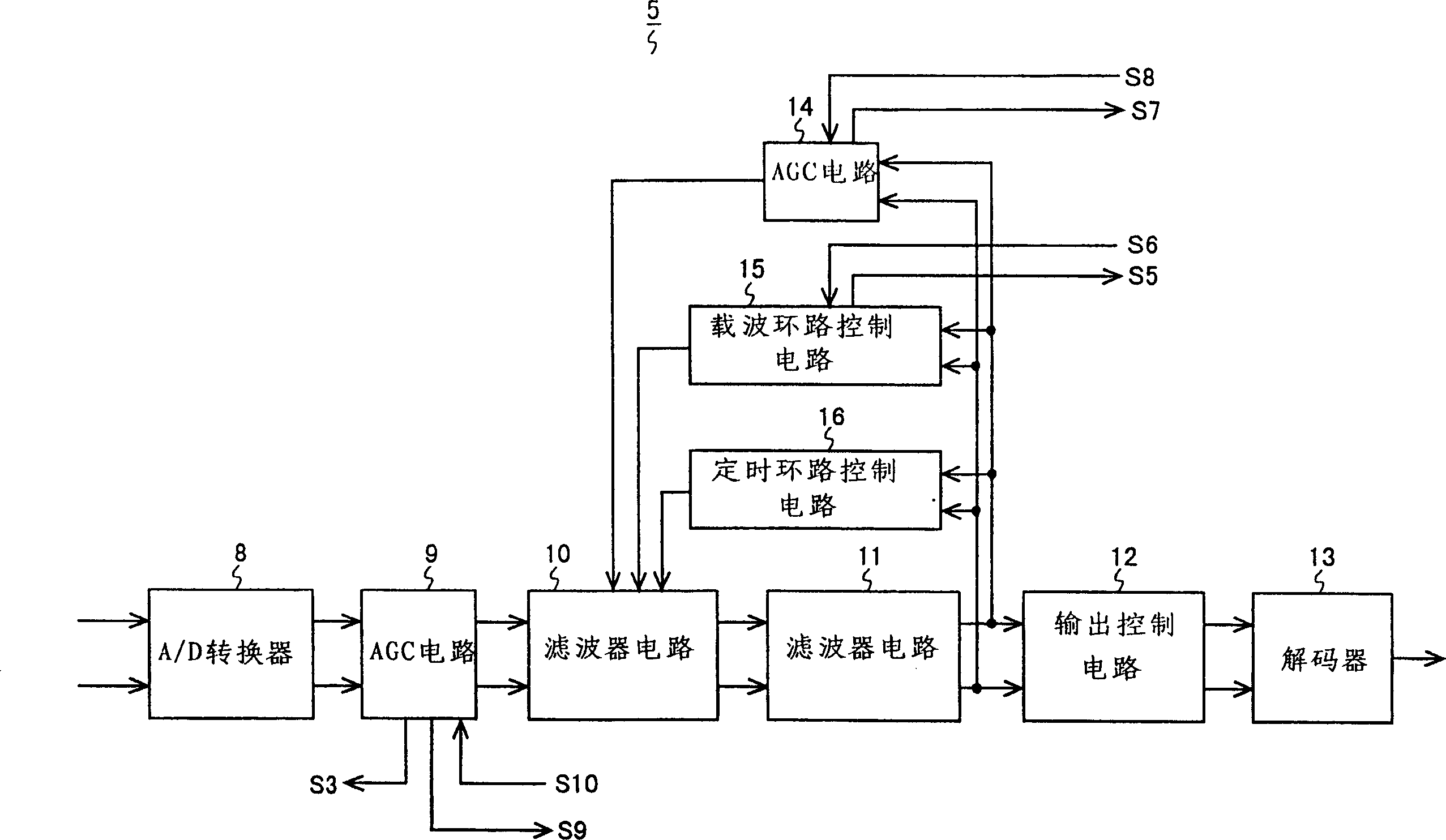
[0024] The digital satellite broadcast receiver 3 of the present invention is equipped with a tuner circuit 4 , a QPSK demodulator circuit 5 , a signal processing circuit 6 and a microcomputer 7 . The intermediate frequency signal output from LNB 2 is sent to tuner circuit 4 . Tuning performed by the tuner circuit 4 is controlled based on the channel frequency data S2 of the channel the user desires to receive fed in from the microcomputer 7 . The gain of the tuner circuit 4 is controlled according to the AGC control signal S3 output from the QPSK demodulator circuit 5 . The intermediate frequency signal is subjected to tuning, amplification, and matrix detection p...


PUM


Abstract

With a conventional digital satellite broadcast receiver, it is occasionally impossible to obtain satisfactory reception performance, as under poor reception conditions. To overcome this, the digital satellite broadcast receiver of the invention has a tuner circuit for selecting a broadcast signal of a desired channel from among signals fed thereto, a demodulator circuit for demodulating the broadcast signal selected by the tuner circuit, and a control circuit, having a reception condition evaluator, for controlling the demodulator circuit by varying the settings thereof according to the reception conditions. This makes it possible to obtain satisfactory reception performance under any reception conditions.

Description

(1) Technical field [0001] The present invention relates to a digital satellite broadcast receiver. (2) Background technology [0002] Fig. 5 shows the configuration of a conventional digital satellite broadcast receiver. A conventional digital satellite broadcast receiver 3' is equipped with a tuner circuit 4, a QPSK (Quadrature Phase Shift Keying) demodulator circuit 5', a signal processing circuit 6, and a microcomputer 7'. The high frequency signal output from the satellite is received by the antenna 1 and then down-converted to an intermediate frequency signal by the LNB (Low Noise Block Converter) 2 . The intermediate frequency signal is then sent to the digital satellite broadcasting receiver 3'. [0003] In the digital satellite broadcasting receiver 3', the intermediate frequency signal is sent to the tuner circuit 4. Tuning performed by the tuning circuit 4 is controlled based on the channel frequency data S2 of the channel that the user desires to receive fed i...

Claims


Application Information

Patent Timeline
IPC IPC(8): H04B1/16H04H40/90H04N5/44H04N5/455H04N5/52H04N7/20
CPCH04H40/90H04N7/20
Inventor 池田仁
Owner SHARP KK
Learn More